You need a reliable Hall effect sensor1 for your new design, but choosing between the A1121 and A1221 is confusing. Making the wrong choice often leads to system failures and wasted production time.
The Allegro A1121 is a Unipolar Switch2 ideal for simple proximity or limit detection; it turns off when the magnet is removed. The A1221 is a Latch sensor3 used for speed sensing with rotating magnets; it requires an opposite magnetic pole to switch states.

I have seen many engineers struggle with this specific choice. In my years at Nexcir4, I have helped clients who bought the wrong sensor because the datasheets looked almost identical. They both come in the same small packages, and they both handle similar voltages. However, their magnetic behavior is completely different. If you pick the wrong one, your machine will not work. Let me break down the differences so you can pick the right part for your project.
What Is the Magnetic Difference Between Unipolar and Latch Sensors?
Many datasheets look identical, which causes frustration for procurement managers and engineers. If you do not understand the magnetic operating points5, your circuit will not behave as expected in the real world.
The main difference lies in the reset mechanism6. Unipolar sensors (A1121) respond to one pole and reset when the field weakens. Latch sensor3s (A1221) require a South pole to turn on and a specific North pole to turn off.

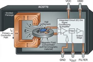
To truly understand which part you need, we must look at how they react to magnetic fields. I often tell my clients to think of the A1121 Unipolar switch like a doorbell. You push the button (bring the magnet close), and it rings. You let go of the button (remove the magnet), and it stops. It is very simple. The A1121 typically responds to a South pole. When the magnetic flux density%%%FOOTNOTE_REF7%%% ($B$) exceeds the operate point ($B{OP}$), the output switches low (turns on). When the magnet moves away and the flux drops below the release point ($B_{RP}$), it switches high (turns off).
On the other hand, the A1221 Latch is like a light switch. You flip it up to turn it on, and it stays on even if you take your hand away. You must physically flip it down to turn it off. In magnetic terms, the A1221 turns on when a South pole approaches. However, removing the magnet does nothing; the sensor stays on (Latched). You must bring a North pole close to the sensor to force it to turn off. This is a critical distinction. If you use an A1221 in a door sensor application, the system will think the door is still closed even after you open it, unless you have a mechanism to introduce a reverse magnetic field.
Here is a simple breakdown of the behavior:
| Feature | A1121 (Unipolar Switch2) | A1221 (Latch) |
|---|---|---|
| Activation | South Pole ($> B_{OP}$) | South Pole ($> B_{OP}$) |
| Deactivation | Remove Magnet ($< B_{RP}$) | North Pole ($< B_{RP}$) |
| Memory | No (Returns to default state) | Yes (Holds state) |
| Magnetic Field | Single polarity needed | Alternating polarity needed |
Understanding this "Memory" effect is key. The Latch has a memory of the last magnetic field it saw. The Unipolar switch does not.
When Should You Use the A1121 Unipolar Switch2?
You need a sensor for a simple door, lid, or mechanical arm position. Using a complex latch sensor here creates unnecessary mechanical design headaches and adds costs to your assembly.
Choose the A1121 for position sensing, limit switches8, and open/close detection. It works perfectly with a simple magnet moving closer and further away, like in laptop screens or industrial valves9.

Based on my experience supplying components to industrial clients, the A1121 is the "go-to" part for limit switches8. A limit switch detects if an object has reached a specific location. Think about a simplified example: a refrigerator door. You want the light to turn on when the door opens. You put a magnet on the door and the sensor on the frame. When the door closes, the magnet comes near, and the sensor detects it. When the door opens, the magnet moves away.
In this scenario, you only want to know if the magnet is there or not. You do not want to engineer a system where a second magnet with a North pole has to swing by to reset the sensor. That would be over-engineering. The A1121 is perfect here because it is a "digital" replacement for a reed switch but with much higher reliability. It does not wear out because there are no moving parts inside the chip.
Another common use I see is in flow switches. A paddle inside a pipe has a magnet attached. When liquid flows, it pushes the paddle and the magnet moves near the sensor. When the flow stops, a spring pushes the paddle back, and the sensor turns off. The A1121 handles this "Presence vs. Absence" logic perfectly. At Nexcir4, we often recommend the A1121 for these applications because it simplifies the mechanical design for our customers. You only need to manage one magnet and one direction of movement.
Why Is the A1221 Latch Best for Speed Sensing?
Your motor application needs precise speed data or commutation. A standard switch misses pulses or creates noise, leading to inaccurate control and motor inefficiency.
The A1221 excels in rotary applications using ring magnets. Its latching nature ensures clean switching between North and South poles, making it perfect for brushless DC motor commutation and tachometers.

When we talk about measuring speed or controlling a motor, we are usually dealing with rotation. In these designs, engineers typically attach a multi-pole ring magnet10 to the rotating shaft. This magnet looks like a donut, but magnetically, it has alternating North and South poles around the edge (N-S-N-S).
This is where the A1221 Latch shines. As the ring spins, the sensor sees a South pole and turns on. As the ring continues to spin, the South pole moves away. If you used an A1121 here, it might turn off as soon as the South pole leaves, even if the North pole hasn't arrived yet. This creates a "gap" or jitter in the signal. However, the A1221 Latch waits. It stays on until the North pole arrives. Then it switches off and stays off until the next South pole arrives.
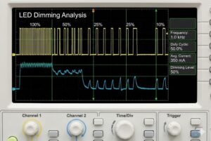
This behavior creates a beautiful, clean square wave signal11 with a 50% duty cycle. This is exactly what a microcontroller needs to calculate RPM (Revolutions Per Minute) accurately. It is also critical for Brushless DC (BLDC) motors. The controller needs to know exactly when to fire the coils to keep the motor spinning smoothly. The A1221 provides that precise timing.
I have seen customers try to use A1121 sensors for speed sensing to save money or consolidate their Bill of Materials (BOM). It rarely works well. The signal becomes unstable if the magnet wobbles even slightly. The A1221 is immune to small wobbles because it requires a strong opposite field to change state.
Application Comparison Table
| Application | Recommended Sensor | Why? |
|---|---|---|
| Speed Sensing (RPM) | A1221 (Latch) | Needs stable switching with ring magnets. |
| BLDC Motor Commutation | A1221 (Latch) | Requires precise timing between N/S poles. |
| Door Open/Close | A1121 (Unipolar) | Simple "Present/Absent" logic. |
| Fluid Flow Meter | A1221 (Latch) | Often uses rotating magnets inside. |
| End-of-Travel Limit | A1121 (Unipolar) | Detects when a moving part stops. |
How Can You Ensure You Get Authentic Sensors?
You found a cheap stock of sensors, but they fail during testing. Counterfeit chips ruin production schedules and damage your reputation with your customers.
Always source from distributors who guarantee traceability12. At Nexcir4, we only supply parts from authorized channels to ensure the silicon inside matches the datasheet specifications13 perfectly.

The market for Hall effect sensor1s is flooded with generic clones and counterfeits. This is a major pain point for the procurement managers I work with. A fake sensor might look exactly like an Allegro A1221 on the outside. The package dimensions might be correct, and the markings might even look legitimate. However, the silicon die inside is often inferior.
The most common issue with fake parts is the magnetic threshold14. An authentic A1221 might be guaranteed to switch at 40 Gauss. A fake one might need 100 Gauss. This means your magnet might be too weak to trigger the fake sensor, causing your motor to stall or your limit switch to fail. Even worse, I have seen fake "Latch" sensors that actually behave like "Unipolar" switches inside. Imagine installing thousands of these into motors, only to find out they don't work because the internal logic is wrong.
At Nexcir4, we take this very seriously. Our team has over 20 years of experience. We know that a cheap chip is the most expensive chip if it fails. We verify our sources. We ensure that if you order an A1121 for a safety-critical limit switch, you get a genuine A1121 that performs exactly as the datasheet says. We also help with alternatives. If the A1221 is End-of-Life (EOL)15 or has a long lead time, we can use our technical knowledge to suggest a valid replacement from a reputable brand, rather than risking your production on gray-market parts16.
Conclusion
To summarize: use the A1121 (Unipolar) for simple position detection like limit switches8, and use the A1221 (Latch) for rotary applications like speed sensing. If you need help sourcing these authentic components, contact Nexcir4 today.
Understanding the basic functionality of Hall effect sensors is crucial for selecting the right component for your design. ↩
Learn about the Unipolar Switch to determine if it's suitable for your proximity or limit detection needs. ↩
Explore the functionality of Latch sensors to see if they meet your requirements for speed sensing with rotating magnets. ↩
Discover how Nexcir can help you source authentic Hall effect sensors and provide technical support. ↩
Understanding magnetic operating points is essential for ensuring your circuit behaves as expected in real-world applications. ↩
Learn about the reset mechanism differences to avoid system failures and wasted production time. ↩
Understanding magnetic flux density helps in selecting the right sensor for your application. ↩
Learn how Hall effect sensors enhance the reliability and functionality of limit switches in various applications. ↩
Explore the application of Hall effect sensors in industrial valves for reliable position sensing. ↩
Learn how multi-pole ring magnets are used in rotary applications for precise speed sensing. ↩
Discover the importance of square wave signals for accurate RPM calculations and motor control. ↩
Explore the importance of traceability to ensure you receive authentic and reliable components. ↩
Learn how datasheet specifications ensure your sensor performs as expected in your application. ↩
Understanding magnetic thresholds is crucial for ensuring your sensor triggers correctly in your application. ↩
Learn about EOL and how it affects the availability and sourcing of Hall effect sensors. ↩
Explore the risks associated with gray-market parts and how they can compromise your design. ↩