Confused by complex circuit diagrams1? This can delay your projects and cause costly errors. This guide is your key to understanding every electronic symbol with ease.
To master electronic and schematic symbols, you must learn the visual language of electronics. This guide provides a comprehensive reference for common components like resistors2, capacitors3, diodes4, and transistors5, helping you read any schematic diagram accurately and efficiently.

I remember my first time looking at a complex schematic. It was overwhelming. But once you learn the basic building blocks, it all starts to make sense. These symbols are the alphabet of electronics. Let's start by breaking down the most common ones you'll encounter. Ready to dive in?
What Are the Symbols for Passive Components Like Resistors and Capacitors?
Do you ever mix up symbols for resistors2, capacitors3, and inductors6? This simple error can cause circuit failure7 and waste hours. Let's master these fundamental symbols now.
The symbol for a resistor is a zigzag line (US) or a rectangle (IEC). A capacitor is shown as two parallel lines, one of which may be curved. An inductor is represented by a series of coils or loops. These symbols denote their function within a circuit.

Understanding passive components is the first step. These parts don't generate energy; they only store, dissipate, or release it. They are the most basic building blocks in almost every circuit I've ever designed or sourced parts for. Let's break them down.
Resistors
Resistors are fundamental. They limit the flow of current. You will see two main styles. The American standard (ANSI) uses a zigzag line. The international standard (IEC) uses a simple rectangle. It's important to recognize both, especially when you work with schematics from different regions. A variable resistor, or potentiometer, adds an arrow pointing to the symbol. This shows that its resistance can be adjusted, which is useful for things like volume controls.
Capacitors
Capacitors store energy in an electric field. The basic symbol is two parallel lines. For polarized capacitors8s](https://arxiv.org/html/2409.16476v1)%%%FOOTNOTE_REF_3%%%, like electrolytic ones, one line is curved or has a plus sign. This is critical. Connecting a polarized capacitor backward can destroy it and potentially damage other parts of your circuit. I've seen projects fail just because an engineer mixed up a polarized and non-polarized capacitor symbol.
Inductors
Inductors store energy in a magnetic field, which is created by current flowing through them. Their symbol looks like a series of coils, which directly represents how they are made. They are essential in power supplies and radio frequency (RF) circuits.
Here is a quick reference table:
| Component | US/ANSI Symbol | IEC Symbol | Description |
|---|---|---|---|
| Resistor | Zigzag Line | Rectangle | Limits current flow. |
| Capacitor | Two Parallel Lines | Two Parallel Lines | Stores electrical energy. |
| Polarized Capacitor | Parallel Lines (one curved/+) | Rectangle with + | Must be connected with correct polarity. |
| Inductor | Coiled Line | Coiled Line | Stores energy in a magnetic field. |
Paying attention to these small details is what separates a good design from a faulty one.
How Do You Identify Diodes and Transistors in a Schematic?
Are you baffled by the different arrows in semiconductor symbols? Misinterpreting them can instantly fry your components. Let's clarify the symbols for diodes4 and transistors5 right now.
A diode is a triangle pointing to a line, showing the direction of current flow. A transistor is more complex, with three terminals (Base, Collector, Emitter). The arrow on the emitter indicates if it's NPN (pointing out) or PNP (pointing in), which is crucial for function.

Semiconductors are the active components, the brains of modern electronics. They can act as switches9 or amplifiers. Their symbols contain vital information about their function, especially the direction of current. Getting these right is non-negotiable for a working circuit.
Diodes
A diode allows current to flow in only one direction. The symbol is a triangle (the anode) pointing at a line (the cathode). The arrow of the triangle shows the direction of conventional current. There are variations for specialized diodes4. A Zener diode10 has a small "Z" shape on the cathode line and is used for voltage regulation. A Light-Emitting Diode (LED11) has two small arrows pointing away from it, showing it emits light.
Bipolar Junction Transistors12 (BJTs)
BJTs are three-terminal devices used for switching or amplification. The key is the arrow on the emitter. For an NPN transistor, the arrow points 'N'ot 'P'ointing 'I'n (outward). For a PNP transistor, the arrow 'P'oints 'I'n 'P'roudly (inward). This simple mnemonic saved me countless hours in my early days. Mistaking an NPN for a PNP is a classic beginner mistake that will prevent the circuit from working.
Here’s a table for quick identification:
| Component | Symbol Description | Key Feature |
|---|---|---|
| Diode | Triangle pointing to a line. | Arrow shows current direction. |
| Zener Diode | Diode symbol with a Z-shaped line. | Used for voltage regulation. |
| LED11 | Diode symbol with arrows pointing out. | Emits light when current flows. |
| NPN Transistor | Base, Collector, and Emitter with arrow pointing out. | Arrow 'Not Pointing In'. |
| PNP Transistor | Base, Collector, and Emitter with arrow pointing in. | Arrow 'Points In Proudly'. |
Always double-check the arrow on the transistor symbol before you finalize your design or start soldering. It's a small detail that defines the entire function of that part of the circuit.
What Do the Different Power and Ground Symbols Mean?
Confused by the various ground symbols13 on a single diagram? Using the wrong one can introduce noise or create safety hazards. Let's clarify these essential power symbols14.
A DC voltage source15 is often shown as a circle with '+' and '-' signs, or as long and short parallel lines (battery). Ground symbols vary: Chassis ground connects to the enclosure, Earth ground to the physical earth, and Signal/Digital ground is a reference point for signals.

Every circuit needs power to operate and a stable ground as a reference point. These symbols might seem simple, but their correct usage is critical for a functional and safe design. As a component sourcing partner, we often see issues arise not from the component itself, but from how it's implemented in the power and ground scheme.
Power Sources
Power sources provide the energy for the circuit. A DC source can be a circle with plus and minus terminals. A battery is often shown as a set of long and short parallel lines, where the long line is the positive terminal. An AC source16 is a circle with a sine wave inside it. You'll also see simple labels like "VCC" or "+5V" which are arrows pointing to a power rail, a common practice to simplify complex diagrams.
Ground Symbols
Ground is the zero-volt reference point. However, not all grounds are the same.
- Earth Ground: Connects physically to the earth. This is primarily for safety, protecting users from electric shock.
- Chassis Ground: Connects to the metal frame or enclosure of the device. This can help with shielding from external noise.
- Signal/Digital Ground: A reference for low-power signals. It's crucial to keep this separate from noisy power grounds to maintain signal integrity. I learned this the hard way on an audio amplifier project where power ground noise was leaking into the audio signal, creating a constant hum.
| Symbol Type | Visual Description | Purpose |
|---|---|---|
| DC Source | Circle with +/- or parallel lines. | Provides constant voltage. |
| AC Source | Circle with a sine wave. | Provides alternating voltage. |
| Earth Ground | Three horizontal lines of decreasing length. | Safety connection to the earth. |
| Chassis Ground | A rake-like symbol. | Connection to the device's frame. |
| Signal Ground | A downward-pointing triangle (often hollow). | 0V reference for signals. |
Proper grounding is an art. In mixed-signal designs, keeping analog and digital grounds separate until they meet at a single "star" point is a key strategy to reduce noise.
How Do You Read Symbols for Switches, Relays, and Logic Gates?
Do the abstract shapes for logic gates17 and switches9 confuse you? Not understanding them makes it impossible to trace the logic flow. Let's simplify these control symbols now.
A simple switch is a broken line with a hinged section that can close the circuit. A relay uses a coil symbol next to a switch, showing it's electromagnetically operated. Logic gates have distinct shapes: AND is a 'D' shape, OR is curved, and NOT is a triangle with a circle.

These components control how and when electricity flows, forming the decision-making part of a circuit. Understanding them is key to understanding a circuit's behavior, from a simple push-button light to a complex microprocessor.
Switches and Relays
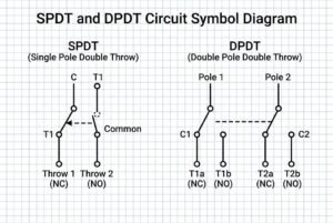
A switch manually opens or closes a circuit. The simplest is a Single-Pole, Single-Throw (SPST) switch. It's just a break in the line with a hinged section. A Single-Pole, Double-Throw (SPDT) switch directs current to one of two paths. A relay is an automated switch. Its symbol shows a coil (the input) and a separate switch (the output). When current flows through the coil, it creates a magnetic field that closes the switch. This is great for using a low-power signal from a microcontroller to control a high-power circuit like a motor.
Logic Gates
Logic gates are the building blocks of digital electronics. Each has a unique shape representing its function.
- AND Gate: The output is high only if all inputs are high. The symbol is shaped like a capital 'D'.
- OR Gate: The output is high if at least one input is high. The symbol has a curved input side and a pointed output.
- NOT Gate (Inverter): The output is the opposite of the input. It's a triangle with a small circle (a bubble) at the output.
| Component | Shape | Function |
|---|---|---|
| SPST Switch | Hinged line break. | Simple on/off connection. |
| Relay | Coil symbol next to a switch symbol. | Electrically operated switch. |
| AND Gate | D-shaped body. | Output is 1 if all inputs are 1. |
| OR Gate | Curved input, pointed output. | Output is 1 if any input is 1. |
| NOT Gate | Triangle with a bubble. | Inverts the input signal. |
The little bubble on the NOT gate is important. You'll see it on other symbols too, and it almost always means "invert" or "active low." It's a small detail with a huge impact on the logic.
Conclusion
Mastering these symbols transforms confusing diagrams into clear instructions. This guide is your first step toward reading any electronic schematic with confidence and building reliable circuits.
Explore this resource to gain clarity on circuit diagrams and avoid costly errors in your projects. ↩
Learn about resistors and their symbols to improve your circuit design skills. ↩
Discover the various capacitor symbols and their functions to avoid mistakes in your projects. ↩
Explore this resource to understand diode symbols and their applications in circuits. ↩
This link will help you master transistor symbols, essential for any electronics project. ↩
Understanding inductors is crucial for circuit design; this resource will clarify their symbols and functions. ↩
This resource will help you identify and prevent common circuit failures, ensuring project success. ↩
Learn about polarized capacitors to avoid damaging your circuits with incorrect connections. ↩
Learn about switch symbols to enhance your ability to read and design circuits. ↩
Explore this resource to understand Zener diodes and their role in voltage regulation. ↩
Learn about LEDs and their symbols to effectively incorporate them into your designs. ↩
This link will provide insights into BJTs, essential for understanding modern electronics. ↩
Understanding ground symbols is vital for circuit integrity; this resource will clarify their meanings. ↩
Gain insights into power symbols to ensure your circuits are designed safely and effectively. ↩
Explore this link to understand DC voltage sources and their importance in circuit design. ↩
Understanding AC sources is crucial for circuit design; this resource will clarify their symbols. ↩
Understanding logic gate symbols is key to digital electronics; explore this resource for clarity. ↩