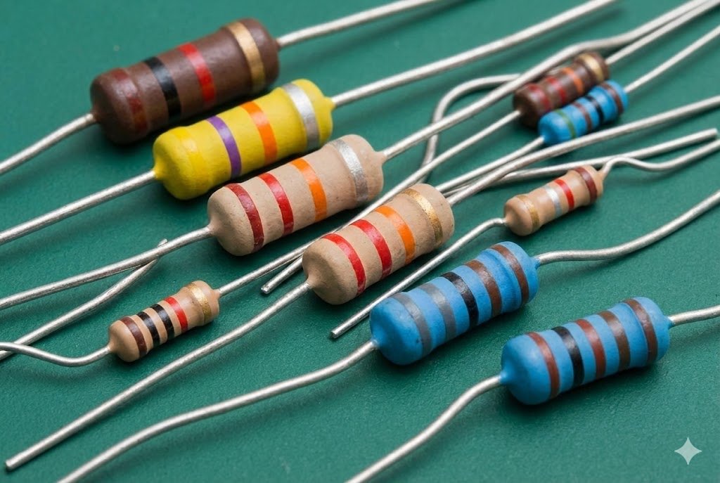
Struggling to read resistor color bands1? This confusion can delay your projects. Our guide simplifies the 4-band, 5-band, and SMD codes for quick and accurate identification.
To master the resistor color code chart2, you need to understand the meaning of each color and its position. For axial resistors, the bands represent significant digits3, a multiplier4, and tolerance. For SMD resistors5, the numbers and letters directly indicate the resistance value. This guide provides charts and examples.
I've been in the electronics industry for over 20 years. I have seen countless engineers, both new and experienced, pause to double-check a resistor's value. It is a fundamental skill, but it is easy to get rusty. Getting it right is critical for every circuit you build. Let's start from the beginning and build your confidence from the ground up.
What are the basics of reading a resistor color code?
Confused by the rainbow of colors? Misreading a band can lead to circuit failure6. Learn the simple mnemonic that unlocks the value of any through-hole resistor instantly.
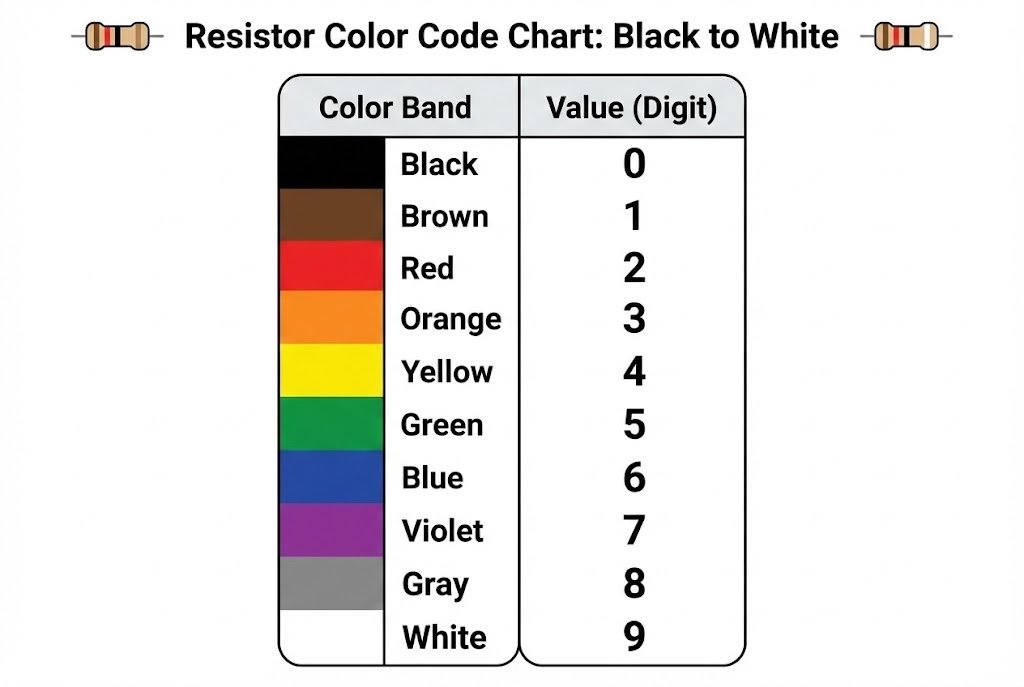
The basics involve a color chart where each color from black to white represents a number from 0 to 9. The bands on a resistor correspond to significant digits3, a multiplier4 (power of ten), and a tolerance percentage. You read them from left to right.
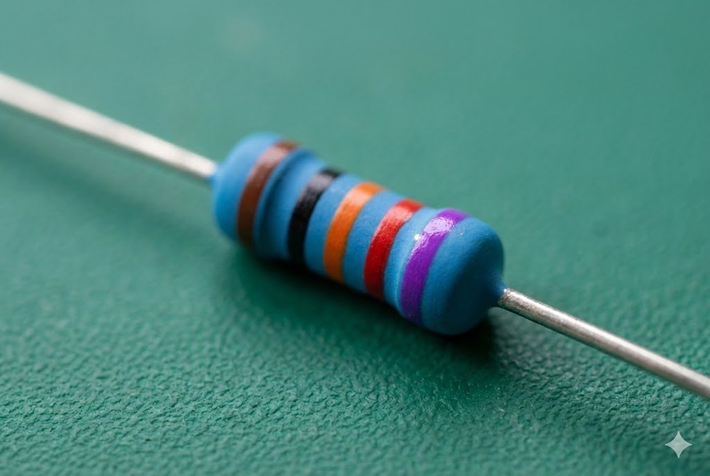
Before you can decode a value, you have to know which way to read the resistor. Look for a band that is gold, silver, or sometimes brown or red and slightly separated from the others. This is the tolerance band7, and it always goes on the right. You read the resistor starting from the opposite end.
The most common way I've taught people to remember the color order is with a mnemonic: Bad Beer Rots Our Young Guts, But Vodka Goes Well. It stands for Black, Brown, Red, Orange, Yellow, Green, Blue, Violet, Gray, White.
Here is a basic chart that forms the foundation for everything else.
| Color | Significant Digit | Multiplier |
|---|---|---|
| Black | 0 | x1 (10⁰) |
| Brown | 1 | x10 (10¹) |
| Red | 2 | x100 (10²) |
| Orange | 3 | x1k (10³) |
| Yellow | 4 | x10k (10⁴) |
| Green | 5 | x100k (10⁵) |
| Blue | 6 | x1M (10⁶) |
| Violet | 7 | x10M (10⁷) |
| Gray | 8 | - |
| White | 9 | - |
Understanding this table is the first step to reading any through-hole resistor.
How do you read a 4-band resistor8 code?
Facing a standard 4-band resistor8? A simple mistake in calculation can ruin your work. Let's walk through a clear, step-by-step process to get it right every time.
For a 4-band resistor8, the first two bands are the significant digits3. The third band is the multiplier4, and the fourth band is the tolerance. Combine the first two digits and multiply by the value of the third band to find the resistance in ohms.
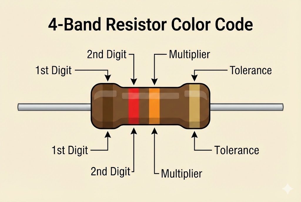
The 4-band resistor8 is the most common type you will find in general electronics. It provides a good balance of cost and precision for most applications. The system is straightforward once you know the rules. The first band is the first digit, the second band is the second digit, and the third band tells you how many zeros to add.
Example: Decoding a 220 Ohm Resistor
Let's take a very common resistor value, 220Ω, and see how it's coded. A 220Ω resistor with a 5% tolerance will have the following bands:
- First Band (1st digit): Red (2)
- Second Band (2nd digit): Red (2)
- Third Band (Multiplier): Brown (x10)
- Fourth Band (Tolerance): Gold (±5%)
To calculate the value, you take the first two digits, which are '2' and '2', to make the number 22. Then you multiply this by the multiplier4 value of the third band. The Brown band means you multiply by 10.
So, the calculation is: 22 x 10 = 220 Ohms.
The fourth band, Gold, tells us the tolerance is ±5%. This means the actual resistance can be anywhere between 209Ω and 231Ω.
When and how do you use the 5-band resistor9 code?
Need more precision in your circuit? Standard resistors won't cut it. 5-band resistor9s offer higher accuracy, but their code is slightly different. Let's master it.
You use 5-band resistor9s for high-precision applications. The first three bands are significant digits3, the fourth is the multiplier4, and the fifth is tolerance. This allows for more specific resistance values and is common for resistors with 1% tolerance or better.
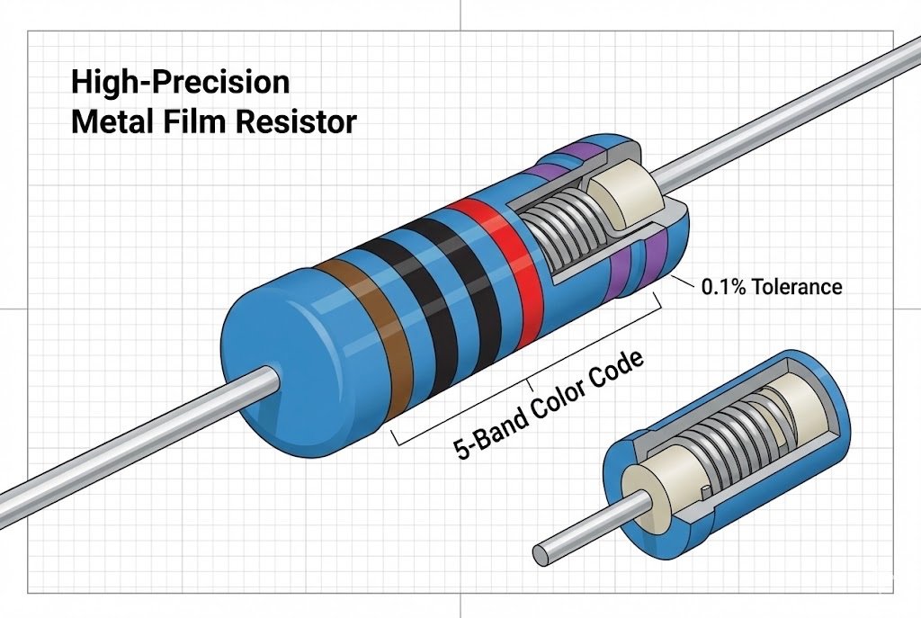
When your design requires a more exact resistance value, you will move from a standard 4-band resistor8 to a 5-band precision resistor. These are common in measurement equipment, medical devices, and audio circuits where accuracy is critical. The extra band allows for a third significant digit.
Why Use 5-Band Resistors?
The key difference is that third significant digit. A 4-band resistor8 with a 5% tolerance might give you a value like 470kΩ. But a 5-band resistor9 can give you a more precise value like 475kΩ. This level of detail is necessary when small variations in resistance can impact the performance of the entire circuit.
Example: Decoding a 1k Ohm Resistor
Let's decode a precision 1kΩ resistor, which is 1,000 Ohms. A typical 5-band version with 1% tolerance would look like this:
- First Band (1st digit): Brown (1)
- Second Band (2nd digit): Black (0)
- Third Band (3rd digit): Black (0)
- Fourth Band (Multiplier): Brown (x10)
- Fifth Band (Tolerance): Brown (±1%)
The calculation is similar, but now we combine three digits. We take '1', '0', and '0' to make the number 100. We then use the fourth band as the multiplier4. A Brown multiplier4 band means we multiply by 10.
So, the calculation is: 100 x 10 = 1,000 Ohms, or 1kΩ. The fifth band, also Brown, indicates a tight tolerance of ±1%.
What does the sixth band on a resistor mean?
Ever see a resistor with six bands? This extra band is often ignored, but it contains critical data. Ignoring it can cause failures in temperature-sensitive applications.
The sixth band on a resistor indicates the Temperature Coefficient of Resistance (TCR). It specifies how much the resistance will change per degree Celsius. This is crucial for high-precision circuits where stability over a range of temperatures is required. Common colors include brown, red, and orange.
A 6-band resistor is essentially a 5-band precision resistor with one extra piece of information. This final band, on the far right, tells you how stable the resistor is with changes in temperature. This is very important in industries like automotive or aerospace, where components must perform reliably in extreme hot and cold environments.
Understanding the Temperature Coefficient (TCR)
The TCR is measured in parts per million per degree Celsius (PPM/°C). For example, a Brown sixth band indicates a TCR of 100 PPM/°C. This means that for every degree Celsius the temperature changes, the resistance will not change by more than 100 parts per million of its total value.
Example: Decoding a 10k Ohm, 100 PPM/°C Resistor
Let's decode a precision 10kΩ resistor with a 100 PPM/°C rating.
- First Band: Brown (1)
- Second Band: Black (0)
- Third Band: Black (0)
- Fourth Band (Multiplier): Red (x100)
- Fifth Band (Tolerance): Brown (±1%)
- Sixth Band (TCR): Brown (100 PPM/°C)
The resistance calculation is: (100) x 100 = 10,000 Ohms, or 10kΩ. The fifth band tells us it has a ±1% tolerance. The sixth Brown band tells us its resistance is very stable and will drift less than 100 PPM for every degree Celsius change in temperature.
How do you decode SMD resistor codes?
Working with modern PCBs? Through-hole color codes are useless here. SMD components have their own cryptic numbering system. Let's crack the code on these tiny parts.
SMD resistors5 use a 3 or 4-digit code. The first digits are the significant figures, and the last digit is the multiplier4 (the power of 10). For example, '103' is 10 followed by three zeros, which is 10,000 ohms or 10kΩ. An 'R' indicates a decimal point.
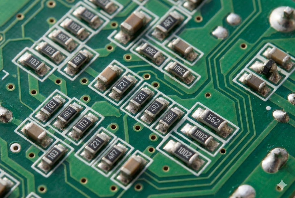
Surface-Mount Device (SMD) resistors are too small for color bands. Instead, they use a numerical code. As a component distributor, we handle these parts every day. Understanding their coding is essential for modern electronics manufacturing and repair.
The 3-Digit and 4-Digit System
This is the most common system for standard SMD resistors5.
- 3-Digit Code: The first two numbers are the significant digits3, and the third is the multiplier4.
221= 22 x 10¹ = 220Ω102= 10 x 10² = 1,000Ω or 1kΩ
- 4-Digit Code: This is used for precision resistors, just like 5-band through-hole parts. The first three numbers are the significant digits3, and the fourth is the multiplier4.
1002= 100 x 10² = 10,000Ω or 10kΩ
The letter 'R' is used to indicate a decimal point for values under 10 ohms.
4R7= 4.7ΩR22= 0.22Ω
An Introduction to the EIA-96 System
For 1% tolerance SMD resistors5, you will sometimes see a different system called EIA-96. It uses a three-character code. The first two characters are a number that corresponds to a three-digit value from a lookup table. The third character is a letter that represents the multiplier4. For example, the code 01Y means:
- 01: This code corresponds to the value
100in the EIA-96 table. - Y: This letter corresponds to a multiplier4 of x0.01.
So,
01Y= 100 x 0.01 = 1Ω. This system allows for more precise values in a very small package.
Conclusion
Mastering resistor codes, from colored bands to SMD numbers, is essential for any electronics professional. This skill ensures circuit accuracy and prevents costly errors in production and prototyping.
Understanding resistor color bands is crucial for accurate circuit design and troubleshooting. ↩
A detailed chart can serve as a quick reference for accurate resistor identification. ↩
Understanding significant digits is key to calculating resistance values correctly. ↩
The multiplier is crucial for determining the actual resistance value of a resistor. ↩
Understanding SMD resistors is essential for modern PCB design and manufacturing. ↩
Understanding the risks can motivate you to learn proper resistor reading techniques. ↩
Knowing about tolerance bands helps in understanding the accuracy of your components. ↩
Learning to read a 4-band resistor can prevent costly mistakes in your electronics projects. ↩
Discovering the differences can enhance your precision in high-stakes electronic applications. ↩


