You choose an IC package, but it causes production delays later. This is a common pain point for engineers, leading to soldering defects1 and severe shortages. I will explain the differences to help you avoid these risks.
SOP-8 is the most common and easiest to solder with a 1.27mm pitch. TSSOP-8 saves space with a 0.65mm pitch but requires precise reflow. QFN offers the best thermal performance2 but is hard to inspect. For supply stability3, always prioritize standard packages like SOP-8 over unique shapes.

I have seen many projects fail because the engineer chose a component that looked good on paper but was impossible to buy. I want to share my experience so you can make safer choices.
Why Is SOP-8 Still the Most Reliable Choice for General Designs?
SOP-8 is the industry standard, but why do manufacturers still love it? It is large, robust, and very easy to handle during the assembly process.
SOP-8 (Small Outline Package) features a 1.27mm lead pitch and gull-wing leads. This wide spacing minimizes solder bridging risks and allows for easy visual inspection. It is the safest choice for consistent supply chains because almost every chip manufacturer produces this format.

At NexCir, I often advise clients to stick to the basics. The SOP-8 package is a perfect example of "old but gold." When you look at the technical specifications, the key feature is the 1.27mm pitch. This distance between pins is huge in the world of electronics. It means your manufacturing factory does not need expensive, high-precision equipment to mount it. Even if you are building a prototype by hand, you can solder an SOP-8 chip with a standard iron.
From a sourcing perspective, SOP-8 is the king of compatibility. If a specific chip from Brand A goes out of stock, there is a 90% chance that Brand B makes an equivalent chip in the exact same SOP-8 footprint. This makes finding alternatives very easy. You do not need to redesign your PCB layout. You simply change the part number on your BOM (Bill of Materials). This flexibility is why I tell my OEM customers to use SOP-8 for power management ICs and standard logic gates. It keeps your costs low and your production line running.
| Feature | Description |
|---|---|
| Full Name | Small Outline Package |
| Pin Pitch | 1.27 mm (Standard) |
| Mounting | Surface Mount (SMT) |
| Sourcing Status | Highly Available / Multi-source |
| Main Advantage | Easy to solder, easy to replace |
When Should You Switch to TSSOP-8 for Space Constraints?
Sometimes your board is too small for SOP-8, so you look at TSSOP-8. This package reduces the footprint significantly, but does it increase your defect rate?
TSSOP-8 (Thin Shrink Small Outline Package) reduces the pitch to 0.65mm and lowers the profile height. It saves about 50% of the PCB area compared to SOP-8. However, the tighter spacing increases the risk of solder bridges, requiring higher quality solder paste stencils.

I remember a specific case with a customer designing a portable medical device. They needed to fit everything into a very slim case. The SOP-8 was too tall and too wide. We recommended the TSSOP-8. The "T" stands for Thin, and the "S" stands for Shrink. It is literally a shrunken version of the standard package. The body width is usually 4.4mm for SOP-8, but only 3.0mm or 4.4mm for TSSOP-8, with a much lower height.
However, you must be careful with the assembly. Because the pins are only 0.65mm apart, the solder paste must be applied perfectly. If the stencil is too thick, the solder will flow between the pins during the reflow oven process. This creates a short circuit called a "bridge." You cannot easily fix this by hand. Furthermore, from a purchasing view, TSSOP-8 is widely available, but slightly less common than SOP-8. You might find fewer direct drop-in replacements if the main chip becomes obsolete (EOL). You need to verify the exact body width, as some TSSOPs come in different widths.
Comparison of Dimensions
- SOP-8 Pitch: 1.27 mm
- TSSOP-8 Pitch: 0.65 mm
- Assembly Risk: TSSOP requires tighter process control.
- Space Savings: TSSOP saves roughly 30-50% board space.
Is QFN Worth the Risk for Thermal Performance?
QFN packages look sleek and modern, but they hide a complex challenge. Do you really need the thermal benefits, or are you creating a testing nightmare?
QFN (Quad Flat No-lead) has no visible leads and uses a large thermal pad on the bottom. It offers superior heat dissipation and electrical performance for high-frequency signals. However, you cannot inspect the solder joints visually; you must use X-ray machines to verify the connection.

I often see engineers choose QFN (or DFN) packages for simple regulators because they look "cool" or modern. This is often a mistake unless you truly need it. The QFN package is excellent for power chips and high-frequency communication modules. The large metal pad on the bottom connects directly to the PCB ground plane. This acts like a heat sink, pulling heat away from the silicon die very efficiently. It also reduces inductance, which is good for RF (Radio Frequency) circuits.
But here is the problem I face in the supply chain: QFN pinouts are often unique to the manufacturer. Unlike SOP-8, which is standardized, a QFN-8 from Texas Instruments might have a slightly different pad shape or size than a QFN-8 from Analog Devices. This makes cross-referencing very difficult. If your chosen QFN part goes on allocation (shortage), you might be stuck. You cannot just swap in a competitor's part without changing the PCB layout. Also, if your factory does not have X-ray inspection capabilities, they cannot guarantee the soldering quality. You might send bad boards to your customers.
Key Considerations for QFN
- Thermal Path: Requires vias in the PCB pad to transfer heat.
- Inspection: Visual inspection is impossible; X-ray is mandatory.
- Rework: Very difficult to desolder and replace by hand.
- Sourcing: High risk of "single-source" dependency.
How Does Package Selection Impact Your Supply Chain and Costs?
Design engineers often ignore the price and lead time of specific packages. How does choosing a non-standard package destroy your production schedule and budget?
You must prioritize "General Packages" over "Odd Shapes" to ensure long-term supply stability3. Standard packages like SOP-8 allow for easy substitution of brands during shortages. Choosing unique or custom packages locks you into one supplier, leading to long lead times and high prices.

At NexCir, we focus on the lifecycle of components. My biggest insight for you is this: Do not design for the datasheet; design for the supply chain. When you select a component, you look at the voltage and current. But you must also look at the package popularity. If a chip comes in a strange, proprietary package size that only one factory in the world makes, you are taking a huge risk. If that factory has a fire or stops production, your product dies.
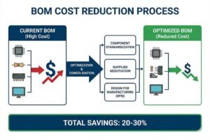
Cost is also a major factor. Standard packages are produced in billions. The economies of scale make them very cheap. Special packages require special molds and handling tapes, which increases the unit price. We help customers "scrub" their BOMs. We look for parts that are "Not Recommended for New Design" (NRND) or have volatile lead times. We often suggest changing a QFN part to an SOP or TSSOP equivalent if the thermal performance2 allows it. This simple change can reduce lead times from 50 weeks to 2 weeks because we can source alternatives from multiple global brands.
NexCir Sourcing Strategy Table
| Package Type | Sourcing Risk | Replacement Ease | Cost Trend | Recommendation |
|---|---|---|---|---|
| SOP-8 | Low | High | Low | Highly Recommended |
| TSSOP-8 | Low/Medium | Medium | Medium | Good for space constraints |
| QFN | High | Low | High | Use only if necessary |
| BGA/CSP | Very High | Very Low | Very High | Avoid for simple designs |
Conclusion
SOP-8 is the safest choice for soldering and sourcing, while TSSOP-8 saves space and QFN handles heat. Always choose standard packages to ensure you can find parts when shortages happen.
Understanding soldering defects can help you improve production quality and reduce delays in your manufacturing process. ↩
Explore the significance of thermal performance in IC packages to enhance the reliability and efficiency of your electronic designs. ↩
Learn how choosing standard IC packages can prevent production halts and ensure a steady supply chain for your projects. ↩