Designing a power system is complex. Choosing the wrong component leads to inefficiency, system failure, or damaged equipment. Understanding their core functions makes selection much simpler.
A transformer1 changes AC voltage2 levels. An inverter3 changes DC to AC. A converter4 changes DC voltage5 levels. Knowing which type of power you start with and what you need is the key to choosing the right component for your power management system6.
Choosing the right power component can feel overwhelming. You have transformer1s, inverter3s, and converter4s, and they all manage electricity. But they do very different jobs. If you pick the wrong one, your project could fail before it even starts. I've seen it happen. A simple mistake in a power supply design7 can cause major delays and cost a lot of money. The good news is that once you understand the basic role of each component, you'll know exactly what your project needs. Let's break down each one so you can make the right choice every time.
What Exactly is a Transformer and When Should You Use One?
Your wall outlet provides high-voltage AC power, but your device needs low-voltage AC. This mismatch can be a big problem. A transformer1 is your solution for this specific task.
A transformer1 is a passive electrical device that transfers electrical energy8 from one AC circuit to another. It "transforms" the voltage up or down without changing the frequency. You should use one when you need to change AC voltage2 levels safely and efficiently.

A transformer1 is one of the most fundamental components in power electronics. Its job is simple but critical: change the voltage of an alternating current (AC). It can't create power or change AC to DC. It just adjusts the AC voltage2. I remember a project where a team tried to power a sensitive 12V AC lighting system directly from a 120V line using just resistors. It was a disaster. The resistors got incredibly hot and the voltage wasn't stable. A simple transformer1 would have solved the problem efficiently and safely. That's why understanding its core function is so important.
How Transformers Work
A transformer1 works on the principle of mutual induction. It has two coils of wire, the primary and secondary, wrapped around an iron core. When AC voltage2 is applied to the primary coil, it creates a changing magnetic field in the core. This magnetic field then induces an AC voltage2 in the secondary coil. The voltage change depends on the ratio of turns in the two coils.
Key Selection Criteria
When you are sourcing a transformer1, you need to look at a few key specifications.
| Parameter | Description | Why It Matters |
|---|---|---|
| Turns Ratio | The ratio of windings on the primary coil to the secondary coil. | Determines if it's a step-up (more secondary turns) or step-down (fewer secondary turns) transformer1. |
| Power Rating (VA) | The maximum power (in Volt-Amps) it can handle. | Exceeding this rating will cause overheating and failure. You need to match it to your load's requirements. |
| Frequency | The AC frequency it's designed for (e.g., 50Hz or 60Hz). | Using a transformer1 at the wrong frequency will lead to poor performance and potential damage. |
| Isolation | Whether it provides galvanic isolation9 between primary and secondary. | Isolation transformer1s are critical for safety, as they separate the device from the high-voltage mains power. |
You use a transformer1 when you are staying in the AC world but just need a different voltage level. Think of power adapters for laptops or power supplies for industrial machines. They all start with a transformer1 to get the high wall voltage down to a more manageable level.
How Does an Inverter Fit into Your Power Design?
You have a DC power source like a battery or solar panel. But your appliance needs standard AC power to run. This is a common challenge in off-grid or backup power systems.
An inverter3 is an electronic device that converts direct current (DC) to alternating current (AC). You use an inverter3 when you need to power AC devices from a DC source, such as running home appliances from a car battery or a solar power system.
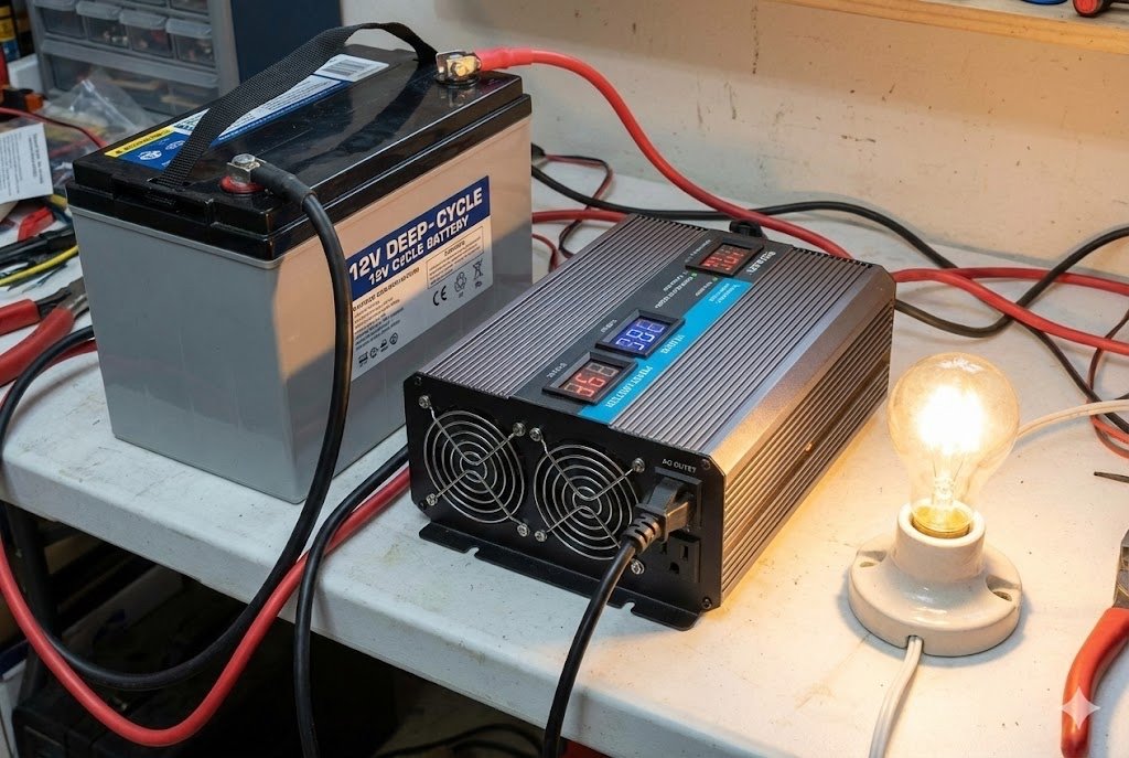
Inverters are the bridge between the DC world of batteries and the AC world of most household and industrial equipment. Without them, things like uninterruptible power supplies (UPS) or solar energy systems wouldn't be possible. The key is that they invert the stable, single-direction flow of DC into the oscillating, back-and-forth flow of AC. In my experience sourcing components for renewable energy projects, choosing the right inverter3 is one of the most critical decisions. The quality of the AC output directly impacts the performance and lifespan of the connected devices.
Types of Inverters
Not all inverter3s create the same quality of AC power. The main difference is the shape of the output waveform.
Modified Sine Wave vs. Pure Sine Wave
| Feature | Modified Sine Wave Inverter | Pure Sine Wave Inverter |
|---|---|---|
| Waveform | A blocky, stepped approximation of a sine wave. | A smooth, clean sine wave, just like utility power. |
| Cost | Less expensive. | More expensive. |
| Compatibility | Works well for simple electronics like lights and motors with brushes. Can cause issues with sensitive electronics. | Compatible with all AC electronics, including sensitive devices like medical equipment, laptops, and audio gear. |
| Efficiency | Generally less efficient. | Generally more efficient. |
For most of our OEM customers building high-reliability products, a pure sine wave10 inverter3 is the only choice. A modified sine wave11 might work for a simple tool, but it can create a buzzing noise in audio equipment or even damage delicate microcontrollers over time. When you need to power sensitive electronics or anything with a motor, always choose a pure sine wave10 inverter3 to ensure clean, stable power.
When is a Converter the Right Choice for Voltage Regulation?
Your design has one main DC voltage5, like 12V from a power supply. But your microcontroller needs 3.3V, and a sensor needs 5V. Supplying these different voltages is a common engineering problem.
A DC-to-DC converter4 is an electronic circuit that converts a source of direct current (DC) from one voltage level to another. It is the right choice when you need to efficiently create multiple DC voltage5 rails from a single DC source within a device.
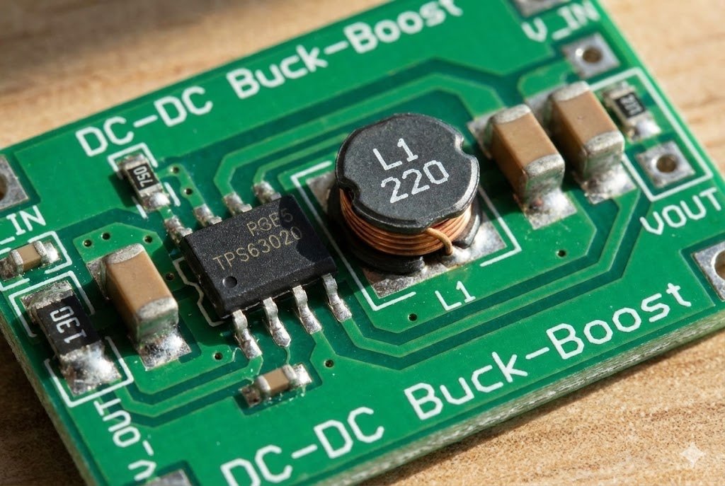
DC-to-DC converter4s are everywhere in modern electronics. They are the workhorses inside your phone, your laptop, and almost any battery-powered device. Their job is to take one DC voltage5 and efficiently change it to another DC voltage5. For example, a car battery provides 12V, but the USB charger in your car needs to output 5V. A DC-DC converter4 does that job. As a component sourcing partner, we help engineers select converter4s all the time. The choice between different types depends entirely on whether you need to step the voltage up, down, or both.
Common Types of DC-DC Converters
These converter4s are essential for power management on a circuit board12. They ensure every part of the system gets the exact voltage it needs to operate correctly.
Buck, Boost, and Buck-Boost
| Converter Type | Function | Input vs. Output Voltage | Common Use Case |
|---|---|---|---|
| Buck Converter | Steps down voltage. | V-out is lower than V-in. | Creating 3.3V or 5V for microcontrollers and logic circuits from a 12V or 24V supply. |
| Boost Converter | Steps up voltage. | V-out is higher than V-in. | Powering an LED backlight (e.g., 20V) from a 3.7V Li-ion battery. |
| Buck-Boost Converter | Can step up or step down. | V-out can be higher or lower than V-in. | Battery-powered devices where the input voltage drops as the battery drains but the output must stay constant. |
When you are designing a circuit, you almost always need different DC voltage5s. Using a separate power supply for each one is inefficient and expensive. Instead, you start with one main DC rail and use buck or boost converter13r](4s">https://arxiv.org/pdf/1607.01538)4s to create the other voltages you need. This is a much more elegant and cost-effective solution for board-level power management.
How Do These Components Work Together in a Real-World System?
You understand each component individually. But how do they connect to build a complete power system? Seeing them in action is the best way to understand their roles and relationships.
In a complex system like a UPS, a transformer1 might step down wall AC, a converter4 rectifies it to DC to charge a battery, and an inverter3 converts that DC back to AC to power devices during an outage. They work in sequence.
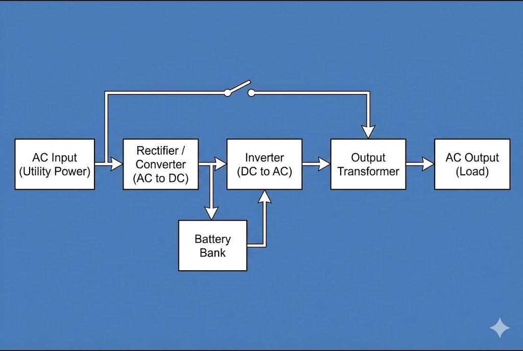
Let's walk through a practical example. Think about an Uninterruptible Power Supply (UPS) for a computer. This device needs to handle both AC and DC power, so it uses all three types of components. When I was helping a client develop a new industrial UPS, we had to carefully source each part of the power train. The reliability of the whole system depended on how well these parts worked together. It’s a perfect illustration of how these components form a complete power management solution.
A Typical Power Flow in a UPS
Here is how the power moves through the system during normal operation and during a power outage.
1. Normal Operation (AC Power is On)
- Input: 120V/230V AC power comes from the wall outlet.
- Transformer: A step-down transformer1 might lower the AC voltage2 to a more manageable level, for example, 24V AC. This is not always present but is common in larger systems for isolation and voltage reduction.
- AC-to-DC Converter (Rectifier): The AC power is then converted into DC power. This DC power does two things:
- Inverter: The inverter3 takes the DC power, cleans it, and converts it back into a perfect, stable AC sine wave.
- Output: This clean AC power is what your computer or server runs on. The UPS continuously provides power from the inverter3, which gives a more stable output than the wall outlet.
2. Power Outage (AC Power is Off)
- Input: The AC power from the wall disappears.
- DC-to-DC Converter (Sometimes): The system instantly switches to the battery. If the battery voltage (e.g., 12V) is different from what the inverter3 needs (e.g., 48V), a boost converter13r](https://arxiv.org/pdf/1607.01538)%%%FOOTNOTE_REF_4%%% will step up the voltage.
- Inverter: The inverter3 continues to run, but now it draws power from the battery instead of the wall. It keeps converting the battery's DC power into stable AC power.
- Output: Your computer never loses power because the inverter3 was already running. The switch from wall power to battery power is seamless.
This example shows that transformer1s, converter4s, and inverter3s aren't competing choices. They are teammates, each with a specific role in managing and converting power from the source to the load.
Conclusion
Transformers, inverter3s, and converter4s each have a unique role. Understanding their functions—AC-to-AC, DC-to-AC, and DC-to-DC—is the key to selecting the right one for your power system design.
Understanding transformers is crucial for efficient voltage management in power systems. ↩
AC voltage is fundamental in power systems; learn how it powers homes and industries. ↩
Inverters are essential for converting DC to AC, enabling the use of batteries and solar power. ↩
Converters are vital for voltage regulation, ensuring devices receive the correct power. ↩
DC voltage is crucial for many electronic devices; understanding it helps in design. ↩
A power management system optimizes energy use; explore its components for better design. ↩
Effective power supply design prevents failures; explore best practices for success. ↩
Understanding energy transfer is fundamental; it helps in designing efficient systems. ↩
Galvanic isolation enhances safety in electrical systems; understanding it is essential. ↩
Pure sine wave inverters provide clean power; essential for sensitive electronics. ↩
Modified sine wave inverters are cost-effective; learn their pros and cons for applications. ↩
Circuit boards house essential components; learn about their roles in electronic devices. ↩
Boost converters are vital for stepping up voltage; learn their applications in electronics. ↩