Are you getting tangled in circuit calculations? A small math error can derail your entire project. Let’s clarify these fundamental formulas for resistors1 and capacitors2 once and for all.
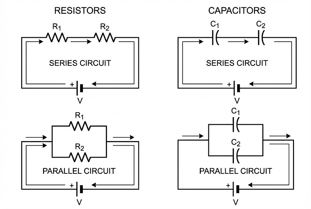
To calculate total resistance3 in a series circuit4, you add the values: R_total = R1 + R2. For parallel, use the reciprocal formula: 1/R_total = 1/R1 + 1/R25. Capacitors are the opposite: add them in parallel (C_total = C1 + C26) and use the reciprocal formula in series.
These rules might seem backward at first, especially when you switch from resistors1 to capacitors2. But there is a clear logic behind how they work. Understanding this logic is more important than just memorizing the formulas. It helps you avoid common mistakes and build more reliable circuits from the ground up. Let's start by looking closely at how resistors1 behave, and you'll see how simple it really is.
How Do You Calculate Total Resistance in Series and Parallel Circuits?
Does it feel strange that adding more resistors1 in parallel actually lowers the total resistance3? This can be confusing and lead to simple but costly errors in your designs.
For resistors1 in a series, you simply add their values: R_total = R1 + R2 + ...Rn. For resistors1 in a parallel configuration, the reciprocal of the total resistance3 is the sum of the reciprocals of each resistor: 1/R_total = 1/R1 + 1/R25 + ...1/Rn.
Let's dive deeper into why these formulas work the way they do. It all comes down to the path that the electrical current takes. I remember early in my career, I spent an entire afternoon debugging a circuit, only to find I had used the series formula for a parallel section. It’s a frustrating mistake, but one that teaches you to double-check the fundamentals.
Resistors in Series: The Single Path
Think of resistors1 in series like toll booths on a single-lane highway. Every car (the current) must pass through every single toll booth. Each booth adds opposition and slows down the traffic. In a circuit, current has only one path to follow through a series of resistors1. Each resistor contributes to the total opposition, or resistance. This is why you simply add their values together. For example, if you have a 100Ω resistor and a 200Ω resistor in series, the total resistance3 is just 100Ω + 200Ω = 300Ω. The current flowing through both resistors1 will be the same.
Resistors in Parallel: Multiple Paths
Now, imagine that same highway, but instead of one lane, you open up multiple new lanes, each with its own toll booth. Even though you've added more toll booths, the overall flow of traffic gets much easier because there are more paths to take. This is exactly what happens with parallel resistors1. You are providing multiple paths for the current to flow. The total current from the source splits, with some going through each branch. Because the current has more options, the total resistance3 of the circuit is actually less than the value of the smallest individual resistor.
| Configuration | Total Resistance Formula | Current Path | Analogy |
|---|---|---|---|
| Series | R_total = R1 + R2 + ... |
Single path for all current | Multiple toll booths on a single-lane road |
| Parallel | [1/R_total = 1/R1 + 1/R2] + ... |
Current splits into multiple paths | Multiple lanes opening on a highway |
Understanding this concept of current paths7 is the key. It moves the formulas from abstract math into a practical, visual concept that you can apply to any schematic.
Why Are Capacitor Calculations the Opposite of Resistors?
You finally master resistor math, and then you see the capacitor formulas. They seem completely backward. This flip can cause major headaches, especially in timing or filtering circuits8.
Capacitors in parallel add their values directly: C_total = C1 + C26 + ...Cn. In series, they follow the reciprocal formula, just like parallel resistors1: 1/C_total = 1/C1 + 1/C2 + ...1/Cn. The reason is that capacitors2 store charge, unlike resistors1 which impede it.
The key is to stop thinking about opposition and start thinking about storage. A capacitor's job is to store electrical energy9 in an electric field. The "size" of a capacitor, its capacitance, tells you how much charge it can hold at a certain voltage. When I was designing my first power supply filter10, this concept finally clicked. I needed more capacitance to smooth out the voltage, so I simply added another capacitor in parallel. The total capacitance increased, and my filter worked perfectly.
Capacitors in Parallel: More Storage Area
Imagine you have a bucket to collect rainwater. The surface area of the bucket's opening determines how much water it can collect. If you place another bucket right next to it, you have effectively doubled your collection area. This is how capacitors2 in parallel work. Each capacitor has two conductive plates. When you connect them in parallel, you are essentially increasing the total surface area of the plates. A larger plate area can hold more charge at a given voltage, so the total capacitance is simply the sum of the individual capacitances. If you connect a 10µF and a 22µF capacitor in parallel, you get a total of 10µF + 22µF = 32µF.
Capacitors in Series: A Thicker Dielectric
Connecting capacitors2 in series is less common, but it's important to understand. Think of a capacitor's plates separated by an insulating material called a dielectric11. When you connect capacitors2 in series, it's like stacking the plates and dielectric11s. The effective distance between the outermost plates increases. A thicker dielectric11 (a larger gap) reduces the capacitance. The total capacitance in a series connection will always be less than the smallest individual capacitor's value. The formula reflects this reduction in storage capability.
| Configuration | Total Capacitance Formula | Effect on Charge Storage | Analogy |
|---|---|---|---|
| Parallel | [C_total = C1 + C2] + ... |
Increases total plate area, holds more charge | Placing buckets side-by-side to collect more rain |
| Series | 1/C_total = 1/C1 + 1/C2 + ... |
Increases effective dielectric11 thickness, holds less charge | Stacking plates, creating a larger gap |
By shifting your thinking from resisting current to storing charge, the capacitor formulas become just as intuitive as the resistor formulas.
How Do These Formulas Affect Real-World Circuit Design?
Knowing the formulas is one thing, but how do they help you build better circuits? Applying them incorrectly can lead to bad performance, signal noise, or even component failure12.
These formulas are the foundation for essential circuit blocks. Series resistors1 create voltage divider13s to scale voltages. Parallel and series capacitors2 are crucial for building filters and timing circuits14 that control system behavior.

Let’s look at two of the most common applications I deal with almost every day: voltage divider13s and simple filters. In my work at Nexcir, we help engineers select the right components for these very applications. Getting the math right at the start prevents costly redesigns and ensures the parts you source will perform as expected. It’s all about building a stable foundation for your design.
Voltage Dividers with Resistors
A voltage divider13 is one of the most useful circuits you can build. It uses two resistors1 in series to produce an output voltage that is a fraction of its input voltage. It’s perfect for tasks like scaling a 5V sensor signal down to a 3.3V level that a microcontroller can safely read. The formula is V_out = V_in * (R2 / (R1 + R2)), where R2 is the resistor connected to ground. Here, the series resistance formula R1 + R2 is right in the calculation. If you miscalculate the total resistance3, your output voltage will be wrong, potentially damaging the input pin on your microcontroller or giving you inaccurate readings. We always advise clients to use precision resistors1 for these applications to ensure the voltage division is accurate and stable.
Filters and Timing with Capacitors
Capacitors are the heart of filtering and timing. An RC circuit15, made of a resistor and a capacitor, creates a time delay. The "time constant16" (τ = R * C) determines how quickly the capacitor charges and discharges. This is used everywhere, from making an LED blink to filtering out noise from a power supply. If you need a longer delay, you can either increase the resistance or the capacitance. Adding another capacitor in parallel is an easy way to increase C ([C_total = C1 + C2](https://arxiv.org/pdf/1904.09022)6), which directly increases your time constant16. This is a common technique for tuning filters. For example, if you see high-frequency noise on a power line, adding a small ceramic capacitor in parallel with a larger electrolytic capacitor can help. Their parallel capacitances add up, and they work together to filter a wider range of noise frequencies.
| Application | Key Components | Formula in Action | Practical Use Case |
|---|---|---|---|
| Voltage Divider | Two [resistors] in series | R_total = R1 + R2 is used to find the division ratio. |
Scaling a 5V signal to a 3.3V ADC input. |
| RC Filter/Timer | A resistor and a capacitor | [C_total = C1 + C2] (in parallel) to adjust the time constant16 τ = R * C. |
Smoothing a noisy power supply or setting the blink rate of an LED. |
Conclusion
Mastering these series and parallel formulas for resistors1 and capacitors2 is the foundation for reliable circuit design17. They are the essential building blocks for nearly every electronic device you will create.
Explore various resistor types to choose the right components for your circuit designs. ↩
Understanding capacitors is essential for effective circuit design and energy storage. ↩
Understanding total resistance is crucial for designing efficient circuits and avoiding costly errors. ↩
Learn the series circuit calculations to ensure accurate designs and prevent circuit failures. ↩
This formula is essential for understanding how resistors work in parallel configurations. ↩
This formula is key for calculating total capacitance in parallel, vital for circuit stability. ↩
Understanding current paths is key to designing efficient circuits and avoiding errors. ↩
Filtering circuits are crucial for noise reduction; mastering them can enhance circuit performance. ↩
Learn how capacitors store energy to improve your understanding of circuit functionality. ↩
Designing effective power supply filters is key for stable circuit operation; learn the techniques. ↩
Learn about dielectrics to understand how they affect capacitor performance in circuits. ↩
Understanding the causes of component failure can help you design more robust circuits. ↩
Voltage dividers are fundamental for scaling signals; learn how to implement them correctly. ↩
Timing circuits are essential for many applications; learn how to design them effectively. ↩
RC circuits are crucial for timing and filtering; understanding them enhances your design skills. ↩
The time constant is vital for timing applications; mastering it can improve circuit performance. ↩
Mastering circuit design principles is essential for creating reliable and efficient electronic devices. ↩