Burning out components when testing a new motor driver is frustrating. You want your solenoid to click and your motor to spin, not see magic smoke rising from your PCB.
To choose the right MOSFET1, ensure the drain current rating exceeds your load's peak current and the gate threshold voltage matches your logic level. Always pair it with a fast recovery or Schottky flyback diode2, like a 1N40073 or 1N58194, to suppress voltage spikes and protect your microcontroller5.

I have seen many engineers struggle with these basics during my 20 years in this industry. A simple mistake in component selection6 can ruin a prototype. However, once you understand the physics behind inductive loads7, the solution becomes clear. Let us look closer at the specific components you need to build a reliable circuit.
Why do inductive loads7 like solenoids destroy circuits without protection?
You cut power to a motor, but your microcontroller5 dies instantly. It is a common mystery that stops production lines and causes expensive delays for hardware teams.
The problem is that inductive loads7 store energy in a magnetic field. When power is cut, this field collapses, generating a high-voltage spike8 known as "back EMF9." Without a protection circuit, this spike travels backward, destroying sensitive logic components10.

Understanding the Physics of Failure
At Nexcir, we often help customers troubleshoot why their boards fail after a few hours of operation. The culprit is almost always the inductive kickback11. When you run current through a coil of wire—whether it is inside a solenoid, a relay, or a DC motor—you are building a magnetic field. This is how these devices work. However, physics dictates that current in an inductor cannot change instantly.
When you turn off the switch (or MOSFET1), the resistance goes to infinity, but the current tries to keep flowing. To keep flowing, the voltage must rise. It rises rapidly, often reaching hundreds of volts in a 5V circuit. This voltage looks for the path of least resistance to the ground. If you do not provide a safe path, it will punch through your transistor or fry your microcontroller5.
Below is a breakdown of how different loads behave:
| Load Type | Example | Behavior on Power Cut | Risk Level |
|---|---|---|---|
| Resistive | LED, Heater | Current stops immediately. No stored energy. | Low |
| Inductive | Solenoid, Relay | Magnetic field collapses. Generates reverse voltage spike. | High |
| Capacitive | Capacitor Bank | Voltage drops slowly. Inrush current is the issue here. | Medium |
We recommend treating every motor or solenoid as a potential voltage source. You must design your circuit to handle this energy dump safely. This ensures your product lasts longer and reduces warranty claims.
How do you select the best MOSFET1 for switching high currents?
Choosing the wrong transistor leads to overheating and system failure. It is painful to see a prototype fail because the switch could not handle the current flow.
Select a Logic-Level N-Channel MOSFET12T](https://nexcir.com/finfet-vs-mosfet-why-are-modern-processors-switching-technologies/)%%%FOOTNOTE_REF_1%%% for low-side switching. Look for a Low On-Resistance to minimize heat generation. Ensure the Voltage rating is at least 20% higher than your supply voltage to handle minor fluctuations safely.

The Critical Specs for MOSFET1 Selection
When I advise clients on component selection6, I tell them to look at three main numbers on the datasheet. If you get these right, your driver will run cool and stable.
1. Logic Level vs. Standard Level This is the most common mistake. Standard MOSFET1s need 10V at the Gate to turn on fully. If you use a 3.3V or 5V microcontroller5 (like an Arduino or STM32) to drive a standard MOSFET1, it will only partially open. This increases resistance and makes the part get very hot. You must look for "Logic Level" MOSFET1s that fully switch on at 5V or lower.
2. $R_{DS(on)}$13 (On-Resistance) Think of this as the friction in the pipe. Lower is better. When the MOSFET1 is on, it acts like a small resistor. Power loss is calculated as $I^2 times R$. If your motor draws 2A and your resistance is 0.1 Ohms, you generate heat. We help customers find parts with very low resistance to avoid needing big heatsinks.
3. Continuous Drain Current14 ($I_D$) Do not trust the absolute maximum rating on the first page of the datasheet. That number is for perfect conditions that do not exist in reality. Look at the continuous current rating at a higher temperature, usually 100°C. Always choose a MOSFET1 rated for at least double your actual load current. This provides a safety margin.
| Parameter | What it means | Recommended Value |
|---|---|---|
| $V_{GS(th)}$ | Voltage needed to turn it on | < 3V for Microcontrollers |
| $V_{DSS}$ | Max voltage it can block | > 1.5x Supply Voltage |
| $R_{DS(on)}$13 | Resistance when on | < 50 m$Omega$ (milliohms) |
At Nexcir, we source original MOSFET1s from brands like Infineon and Vishay to ensure these specs are accurate and reliable.
Why is the specific type of flyback diode2 critical for safety?
Using a random diode from your junk box is risky. If it reacts too slowly, the voltage spike will destroy your MOSFET1 before the diode opens.
The flyback diode2 provides a path for the collapsing magnetic field's current to circulate. A standard 1N40073 works for general solenoids, but high-speed PWM motor control requires a Schottky diode like the 1N58194 for faster switching speeds.

Choosing Between General Purpose and Schottky Diodes
The flyback diode2 is also called a snubber or freewheeling diode. It is placed in parallel with the inductive load, but in reverse. Normally, it does nothing. But when the power cuts, the reverse voltage spike forward-biases the diode. The current loops back through the coil and the diode until the energy dissipates as heat.
The 1N40073 Solution For simple applications, like a relay that clicks once every few seconds, or a solenoid door lock, the 1N40073 is the industry standard. It handles up to 1000V implies it is very robust. We ship thousands of these because they are cheap and reliable for low-speed switching.
The Schottky Advantage If you are driving a motor using Pulse Width Modulation (PWM) to control speed, the 1N40073 is too slow. It cannot switch from "blocking" to "conducting" fast enough. For PWM, you need a Schottky diode, like the 1N58194. Schottky diodes turn on instantly and have a lower forward voltage drop (around 0.3V vs 0.7V). This means they waste less energy and protect the circuit better during high-speed switching.
Here is a quick guide I use when helping engineers pick parts:
| Diode Part Number | Type | Max Voltage | Use Case |
|---|---|---|---|
| 1N40073 | General Purpose | 1000V | Relays, Solenoids, Slow switching. |
| 1N4148 | Signal Diode | 100V | Very small loads (relays < 100mA). |
| 1N58194 | Schottky | 40V | DC Motors, PWM control15, Fast switching. |
Using the right diode ensures your MOSFET1 does not see voltage spikes higher than it is rated for. It is a small part that saves the whole board.
When should you use integrated driver ICs like ULN200316 or DRV882517?
Building discrete circuits takes up too much space on the board. Trying to route traces for four separate MOSFET1s and diodes is a nightmare for compact designs.
Integrated Circuits (ICs) combine multiple switches and protection diodes into one chip. The ULN200316 is perfect for driving small stepper motors or relay arrays, while the DRV882517 offers advanced control for higher-power stepper applications.

Simplifying Design with Integrated Chips
Sometimes, building a custom circuit with MOSFET1s and diodes is overkill. If you need to drive multiple loads or control a stepper motor, integrated driver chips are the best choice. They save space, reduce assembly time, and include built-in protection.
The ULN200316: The Relay and Stepper Workhorse The ULN200316 is a Darlington Transistor Array. It contains seven switch channels in one chip. Each channel has a built-in flyback diode2. This is incredibly convenient. If you are driving a 5-wire stepper motor (like the 28BYJ-48) or a bank of 7 relays, this single chip replaces 7 transistors and 7 diodes. It is cost-effective and very easy to layout on a PCB.
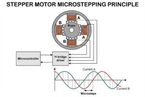
The DRV882517: Precision Motor Control For 3D printers or CNC machines, you need more than just on/off control. You need micro-stepping to get smooth motion. The DRV882517 is a complete stepper motor driver. It handles higher currents (up to 2.5A) and handles all the complex logic of energizing coils in the right sequence. It also has thermal shutdown18 and over-current protection19 built-in.
Comparison of Solutions
| Feature | Discrete MOSFET1s | Integrated IC (ULN200316) | Integrated Driver (DRV882517) |
|---|---|---|---|
| Current Capacity | Very High (10A+) | Low (500mA per channel) | Medium (2.5A) |
| Complexity | High (More parts) | Low (One chip) | Low (One chip) |
| Protection | External Diode Required | Built-in Diodes | Built-in Thermal/Current |
| Best For | Big DC Motors, Large Solenoids | Relays, Small Steppers | Precision Steppers, CNC |
At Nexcir, we stock both the ULN200316 and DRV882517 because they cover 90% of the common driver needs. We ensure these chips are genuine, so your protection features actually work when needed.
Conclusion
To design a safe driver, match your MOSFET1 to the load current and use a 1N40073 or 1N58194 diode. For easier designs, use ULN200316 or DRV882517 chips.
Understanding MOSFETs is crucial for effective circuit design, ensuring your components function correctly and efficiently. ↩
Learn how flyback diodes prevent damage from voltage spikes, ensuring the longevity of your electronic components. ↩
Discover why the 1N4007 is a reliable choice for protecting circuits from voltage spikes. ↩
Learn about the advantages of the 1N5819 for high-speed applications and its role in circuit protection. ↩
Discover the importance of microcontrollers in managing and controlling electronic devices. ↩
Learn effective strategies for component selection to ensure optimal circuit functionality. ↩
Explore the behavior of inductive loads to better design circuits that can handle their unique challenges. ↩
Understanding the sources of high-voltage spikes can help you design more robust circuits. ↩
Understanding back EMF is essential for protecting sensitive components in inductive load applications. ↩
Understanding how to protect sensitive components is crucial for reliable circuit design. ↩
Explore strategies to manage inductive kickback and protect your circuit from damage. ↩
Find out how Logic-Level MOSFETs can improve efficiency in low-voltage applications. ↩
Understanding $R_{DS(on)}$ helps in selecting the right MOSFET to minimize power loss and heat generation. ↩
Learn how to choose a MOSFET with the right current rating to ensure reliable operation. ↩
Learn how PWM control can optimize motor performance and efficiency in various applications. ↩
Explore the benefits of using the ULN2003 for driving relays and stepper motors in compact designs. ↩
Discover how the DRV8825 can enhance precision control in your motor applications. ↩
Understanding thermal shutdown can help prevent overheating and ensure the safety of your circuits. ↩
Learn how over-current protection can safeguard your components from damage during operation. ↩