Are you confused by the "104" printed on a small capacitor? Picking the wrong capacitor type can ruin your circuit design and delay production. I will explain exactly what these codes mean.
The code "104" represents a capacitance value of 100,000 picofarads (pF), which equals 100 nanofarads (nF) or 0.1 microfarads (µF). It is calculated by taking the first two digits (10) and adding the number of zeros indicated by the third digit (4). This is a standard EIA coding system1.

Understanding the code is just the first step. You also need to know the difference between capacitor types. Many engineers make mistakes here. Let us look closer at these differences and how to avoid sourcing headaches.
What does the 104 code actually mean and how do you read it?
You see numbers like 103, 104, or 225 on components. It feels like a secret code. If you misinterpret them, your device will not function correctly.
The three-digit code system is simple once you know the rule. The first two digits are significant figures. The third digit is the multiplier (number of zeros). The result is always in picofarads (pF). For 104: 10 followed by 0000 = 100,000 pF.

I remember when I first started in electronics, I confused pF and nF constantly. It is a common mistake. To help you avoid this, we need to break down the math and the units. The base unit for these codes is always the Picofarad (pF).
Here is how you break down the logic:
- First Digit: 1
- Second Digit: 0
- Third Digit (Multiplier): 4 (This means add four zeros).
So, you write 1, then 0, then 0000. This gives you 100,000 pF.
However, engineers rarely say "one hundred thousand picofarads." We convert it to make it easier to say.
- 1,000 pF = 1 nF (Nanofarad)
- 1,000,000 pF = 1 µF (Microfarad)
Therefore, 100,000 pF divided by 1,000 equals 100 nF. If you divide by 1,000 again, you get 0.1 µF.
This value, 0.1 µF, is the most common decoupling capacitor used in digital circuits. It filters out noise on power lines. If you source the wrong value, your microcontroller might reset randomly.
Here is a quick reference table for common codes I see in BOMs (Bills of Materials) every day:
| Code | Calculation | Value (pF) | Value (nF) | Value (µF) |
|---|---|---|---|---|
| 102 | 10 + 00 | 1,000 pF | 1 nF | 0.001 µF |
| 103 | 10 + 000 | 10,000 pF | 10 nF | 0.01 µF |
| 104 | 10 + 0000 | 100,000 pF | 100 nF | 0.1 µF |
| 225 | 22 + 00000 | 2,200,000 pF | 2,200 nF | 2.2 µF |
| 476 | 47 + 000000 | 47,000,000 pF | 47,000 nF | 47 µF |
Also, watch out for a letter after the number, like "104K". This letter tells you the tolerance.
- J: ±5%
- K: ±10%
- M: ±20%
For general decoupling, "M" or "K" is fine. For precise timing circuits, you need "J" or better. At NexCir, we verify these tolerances strictly because a loose tolerance can cause signal errors in sensitive industrial equipment.
What are the critical differences between ceramic and electrolytic capacitors?
You might think a 10uF ceramic capacitor is the same as a 10uF electrolytic one. This assumption causes voltage bias issues and mechanical failures in the field.
Ceramic capacitors (MLCCs) are non-polarized and great for high frequencies but suffer from DC bias effects. Electrolytic capacitors are polarized, offer high capacitance per volume, but have shorter lifespans and higher ESR. You cannot simply swap them without checking voltage and frequency requirements.

I often see BOMs where a designer tries to replace an electrolytic capacitor with a ceramic one to save space. While ceramic capacitors (MLCCs) are getting better and smaller, they behave very differently under stress.
Let us dig into the technical specs that matter most for OEM manufacturers.
1. DC Bias Characteristic2 (The Hidden Trap) This is the biggest mistake I see. If you buy a 10µF ceramic capacitor rated for 6.3V and apply 5V to it, it might not act like 10µF anymore. High-dielectric constant ceramics (like X5R or X7R) lose capacitance as voltage increases. At 5V, that "10µF" capacitor might only provide 3µF or 4µF of actual capacitance.
- Ceramic: Loses capacitance with voltage.
- Electrolytic: Capacitance stays stable regardless of voltage (until breakdown).
2. ESR (Equivalent Series Resistance)
- Ceramic: Very low ESR. This is great for handling ripple current at high frequencies (like in DC/DC converters).
- Electrolytic: Higher ESR. However, sometimes you need some resistance to keep a power supply control loop stable. If you swap an electrolytic for a ceramic, the ESR might be too low, causing the power supply to oscillate or "ring."
3. Failure Mode
- Ceramic: Fails short. If the capacitor cracks due to board flexing, it creates a short circuit. This can burn the PCB trace or blow a fuse.
- Electrolytic: Usually fails open (dries out) or explodes if over-volted/reverse polarized. They have a limited lifespan, often 2,000 to 10,000 hours at max temperature.
Comparison Table for Selection:
| Feature | Ceramic Capacitor (MLCC) | Electrolytic Capacitor (Aluminum) |
|---|---|---|
| Polarity | Non-Polarized (Safe either way) | Polarized (Must connect correctly) |
| Size | Very Small (0402, 0603) | Larger (Cylindrical cans) |
| Voltage | Low to High (6.3V - 3kV) | Low to High (6.3V - 500V+) |
| Capacitance | Low (pF to ~100µF) | High (1µF to Farads) |
| Lifespan | Long (Decades) | Limited (Dries out over time) |
| Best Use | High-frequency filtering, decoupling | Bulk energy storage, low-frequency filtering |
When NexCir supports your product development, we check these parameters. We do not just look at "10µF 16V." We ask: "Is this for a power input or a signal line?" This helps us recommend the right part that will last for years, not just weeks.
Why are Safety Capacitors (X2/Y2) crucial for your product certification?
Many procurement teams ignore the "X" or "Y" rating to save costs. This leads to failed UL/CE certifications and dangerous electric shock risks for end-users.
Safety capacitors (X and Y Class)3 are designed to fail safely. X capacitors go across the line and prevent fire if they fail. Y capacitors go line-to-ground and prevent shock. You must use certified X2/Y2 parts for AC power inputs to pass regulatory standards.

If you are exporting products to Europe or North America, safety capacitors are not optional. They are a legal requirement. I have seen shipments detained at customs because the power supply lacked the correct safety marks on these specific components.
These capacitors handle high-voltage spikes from the AC grid (like lightning strikes nearby). They are placed in the EMI filter stage, right at the power entry.
The Classification System:
-
X Capacitors (Line-to-Line): These connect between the "Live" and "Neutral" wires.
- Function: They filter out differential mode noise.
- Failure Mode: If an X capacitor fails, it usually shorts out. This blows the fuse. The device stops working, but it does not catch fire and no one gets shocked.
- Common Class: X2 (Withstands pulses up to 2.5kV). This is the industry standard for general wall-plug applications.
-
Y Capacitors (Line-to-Ground): These connect from "Live" to "Earth Ground" or "Neutral" to "Earth Ground."
- Function: They filter out common mode noise.
- Failure Mode: This is critical. If a Y capacitor fails short, the metal casing of your product becomes live with 110V or 220V. This can kill a user. Therefore, Y capacitors are built to never fail short. They fail open.
- Common Class: Y2 (Basic insulation).
Why you cannot use a standard ceramic capacitor here: A standard 104 ceramic capacitor (100nF) might have a rating of 250V. However, it is not certified to handle thousands of volts of lightning surge without breaking down. It does not have the "self-healing" properties of film safety capacitors or the reinforced insulation of safety ceramics.
Certification Marks: When we source these for you, we look for logos on the capacitor body:
- UL (USA)
- VDE (Germany)
- ENEC (Europe)
- CQC (China)
If your BOM lists a generic "100nF 275V" capacitor for the AC input, NexCir will flag this. We will suggest a proper X2-104K-275V component from reputable brands like Murata, TDK, Vishay, or Kemet. This ensures your final product passes UL/CE testing smoothly.
How do you handle component shortages and find reliable alternatives?
Your production line stops because one specific capacitor is out of stock. This is the nightmare of every supply chain manager. You need a backup plan now.
Do not rely on a single brand. Look for cross-references based on specifications: Capacitance, Voltage, Dielectric (X7R vs X5R), and Package size (0603 vs 0402). NexCir helps you identify valid replacements from top manufacturers like Samsung, Yageo, or Walsin to keep lines running.

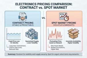
In the last few years, the market for passive components has been volatile. I have seen lead times stretch to 50 weeks for simple automotive-grade capacitors. To survive this, you need a robust "Second Source" strategy.
When we look for alternatives (Cross-References4) for our clients, we follow a strict technical checklist. We do not just guess.
The NexCir Alternative Selection Checklist:
- Package Size: Must be identical (e.g., 0603). The pads on your PCB cannot change.
- Capacitance & Tolerance: Must match (e.g., 100nF ±10%).
- Voltage Rating: Must be equal or higher. If the original is 25V, a 50V alternative is usually fine (and often performs better).
- Dielectric Material: This is non-negotiable.
- If your original is X7R (stable across temperature), you cannot switch to Y5V (very unstable) just to save money. The capacitance will drop drastically when the device gets hot.
- If you need C0G/NP0 (precision), you cannot use X7R.
- Thickness: Sometimes a higher voltage part is thicker. We check if your enclosure has enough clearance.
Example of Cross-Reference Table:
Let us say you need a Murata part that is out of stock. Here is how we map it to others:
| Brand | Part Number | Spec | Status |
|---|---|---|---|
| Murata (Target) | GRM188R71H104KA93D | 0603, 100nF, 50V, X7R | Allocated / Long Lead Time |
| Samsung | CL10B104KB8NNNC | 0603, 100nF, 50V, X7R | Available |
| Yageo | CC0603KRX7R9BB104 | 0603, 100nF, 50V, X7R | Available |
| TDK | C1608X7R1H104K | 0603, 100nF, 50V, X7R | Available |
| Walsin | 0603B104K500CT | 0603, 100nF, 50V, X7R | Available |
A Warning on "Generic" Brands: During shortages, many unknown brands appear. They might offer the "same" spec for half the price. But their failure rates can be high. At NexCir, we stick to verified, Tier-1 and Tier-2 manufacturers. We check the traceability of every reel.
We also monitor Product Lifecycle. If a part is marked "NRND" (Not Recommended for New Design), we will warn you immediately. We will help you select an "Active" part so you do not have to redesign your board next year.
Conclusion
Understanding the 104 code and choosing between ceramic, electrolytic, or safety capacitors is vital for product reliability. NexCir helps you source the right components globally. Upload your BOM today.
Understanding the EIA coding system is crucial for correctly interpreting capacitor values, ensuring your circuit functions as intended. ↩
DC Bias Characteristic can significantly alter the performance of ceramic capacitors, impacting your circuit's reliability and efficiency. ↩
Using the correct safety capacitors is essential for meeting regulatory standards and ensuring user safety in electronic products. ↩
Cross-referencing components helps avoid production delays due to shortages, ensuring your supply chain remains uninterrupted. ↩