Choosing the right microcontroller (MCU) is one of the most important decisions in electronic product design.
The MCU determines not only system performance, but also power consumption, cost, scalability, and long-term product stability.
Whether you’re designing industrial equipment, consumer electronics, IoT devices, or automotive systems, selecting the right MCU can significantly impact the success of your project.
This guide explains the key factors to evaluate and how to choose the MCU that fits your real design needs.
⚙️ 1. Define Your Application Requirements First
Before comparing MCU families, clarify your actual needs.
Key questions:
-
What functions must the MCU control?
-
What is the expected processing performance?
-
Are real-time operations required?
-
How large will the firmware be?
-
What peripherals (UART, SPI, I2C, CAN, ADC) are needed?
-
What environmental conditions will the device operate in?
Clear requirements avoid overdesigning or underpowering the system.
🧠 2. Evaluate Performance (Clock, Architecture, DSP Options)
MCU performance is based on:
✔ Core architecture (ARM Cortex, PIC, AVR, RISC-V)
✔ Clock speed (typ. 8 MHz – 480 MHz)
✔ Pipeline and instruction set
✔ Hardware acceleration (DSP, FPU, AI acceleration)
Industrial automation, motor control, and IoT gateways often require mid–high performance MCUs.
Simple consumer products may run on low-power 8-bit or basic 32-bit MCUs.
💾 3. Choose the Right Memory Size
Firmware grows—always plan buffer.
Memory considerations:
-
Flash for program code
-
RAM for runtime operations
-
EEPROM for data logging
-
External memory options (QSPI Flash, SDRAM)
If your firmware includes communication stacks (BLE, TCP/IP), choose a device with more margin.
🔌 4. Match the MCU With Required Peripherals
MCU peripheral availability is often a deal-breaker.
Common peripherals:
-
UART / USART
-
SPI / I2C
-
ADC / DAC
-
CAN / LIN / FlexRay (automotive)
-
USB / Ethernet
-
PWM for motor control
-
Touch or display interfaces
Make sure:
-
The MCU contains all needed peripherals
-
The number of instances is sufficient
-
The pin mapping is practical
🔋 5. Evaluate Power Consumption
For battery-powered or wearable products, power is critical.
Consider:
-
Active mode current
-
Sleep / deep sleep current
-
Wake-up latency
-
Power domains
-
Built-in PMU capability
Ultra-low-power MCUs (e.g., STM32L series, NXP Kinetis L) are ideal for IoT sensors and portable devices.
🧩 6. Consider Package Type and Size
Package choice affects assembly cost and PCB design.
Common packages:
-
DIP (prototypes)
-
QFP
-
QFN
-
BGA (high-performance or space-limited designs)
High-density BGAs offer more I/O but require complex manufacturing.
🔄 7. Ensure Long-Term Availability and Lifecycle Stability
Designing a product around a soon-to-be-discontinued MCU is risky.
Check:
-
Manufacturer lifecycle policy
-
AEC-Q100 (for automotive)
-
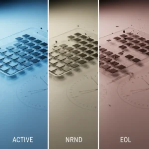
NRND/EOL notices
-
Typical production span for the family
STM32, PIC, Renesas, and NXP families have long lifecycles suitable for mass production.
💵 8. Balance Cost vs. Capability
The most expensive MCU is not always the best solution.
Consider:
-
Unit cost
-
Availability
-
Required vs. actual performance
-
Required vs. actual peripherals
-
Alternatives or cross-vendor twins
A balanced choice saves cost without compromising performance.
🛠️ 9. Evaluate Ecosystem and Development Tools
Strong ecosystems reduce development time.
Consider:
-
IDE/toolchain support
-
Middleware and libraries
-
RTOS compatibility
-
Community ecosystem
-
Reference designs and sample code
This is a major reason STM32, PIC, and ESP32 dominate many markets.
🧾 Conclusion
Choosing the right MCU requires balancing performance, memory, peripherals, power efficiency, development ecosystem, and long-term availability.
By carefully evaluating these factors, designers can create reliable, scalable products that avoid redesigns and reduce development risk.