
Why the Ordering Code, Not Just the Generic Part Name, Belongs on the Line Item
A BOM line that reads only "ATmega32A" tells a buyer almost nothing about what will arrive in the box. It names a device, not an orderable item. The ordering code ATMEGA32A-AU from Microchip Technology Inc. is the string that fixes the physical part: an AVR 8-bit microcontroller in a 44-lead TQFP package, supplied to an industrial-grade temperature range.
That distinction matters at every hand-off in the procurement chain. An engineer specifies a design around a particular footprint and a particular environmental envelope. A buyer converts that design into a purchase order. A contract manufacturer loads a feeder and a reflow profile against it. If the line item carries only a family-level description, each of those steps has to guess at the same two details — package and temperature grade — and each has an opportunity to guess differently.
Putting the full ordering code on the line item closes that gap. It also makes the BOM self-documenting: anyone reviewing the part later can see from the code alone that a specific package and a specific grade were intended, rather than having to reconstruct intent from a footprint drawing or an email thread.

A second reason is change control. When the code is on the line item, any substitution becomes a visible edit to a defined string. When it is not, a substitute can slip in under the same generic name and still look like a match on paper. The part number is the smallest unit of control a BOM has, and it only works if it is used in full.
Decoding ATmega32A-AU: 44-Lead TQFP, Package Type 44A
The ordering code is best read as a whole rather than as a puzzle of individual letters, because the code as a whole is what fixes the physical attributes a buyer needs to check.
For ATMEGA32A-AU, the code fixes:
- Package: 44-lead TQFP, package type 44A
- Pin count: 44
Two things follow immediately for anyone maintaining the BOM.
First, the footprint check becomes mechanical. The land pattern on the board must correspond to a 44-lead TQFP, and the assembly house must have that package type in its approved tooling and inspection programme. A reviewer who sees the full ordering code does not need to consult a family nickname to know which package outline to check against — the package type is part of the coded item.
Second, the pin count gives a fast sanity check against the schematic symbol and the netlist. A 44-pin device with 32 programmable I/O lines means the remaining pins carry the supply, ground, reset, clock and programming functions. If a symbol on the schematic expects a different pin count, the mismatch is visible before a single board is built, not after the first prototype run.
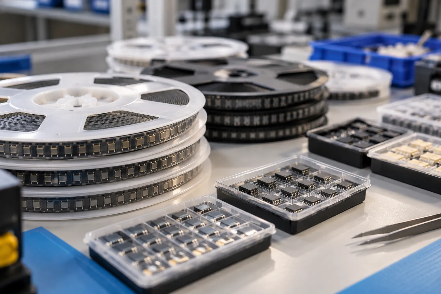
It is worth writing the package description next to the code in the BOM's description column, even when the code itself is complete. The description is what a human reader scans; the code is what the purchasing system acts on. Keeping both aligned means an engineer and an ERP record say the same thing.
Temperature Grade and Supply Voltage Fields to Record
Alongside the ordering code, two electrical and environmental fields belong on the line item: the operating temperature range and the operating voltage range.
Operating temperature range (TA, industrial grade): −40 to +85 °C. Recording this as an explicit field rather than as an assumption protects the design intent. The number is part of what the AU ordering code identifies, and it is the value against which enclosure temperatures, thermal rise on the board, and the end product's declared operating environment should be assessed. If a design needs to operate outside that band, the requirement is real and should be raised during specification, not discovered during a qualification run.
Operating voltage range (VCC): 2.7 to 5.5 V. This range defines the rails the device can be run from and therefore which power architecture the board can use. Recording it beside the code lets a reviewer confirm, without opening the datasheet, that the supply design falls inside the permitted range.
One further field is easy to overlook: the datasheet's DC characteristics and start-up tables are recorded at a VCC test condition of 5.0 V. That is a test condition, not a restriction on the operating range, and the two should not be conflated on a BOM review. When a reviewer is checking whether a datasheet figure applies to their design, the first question is which rail the figure was taken at. Noting the 5.0 V test condition beside the line item saves that step and prevents a number measured at one rail from being read as a guarantee at another.
The maximum oscillator frequency carries a related condition: 16 MHz at VCC = 4.5 V to 5.5 V. It is a frequency tied to a supply window, and it belongs in the same discussion as the voltage field rather than being recorded as an unconditional headline figure.
The Other Figures to Record with the Code
The remaining on-chip figures are collected below as a single reference table. The point is confirmation, not instruction: a reviewer should be able to hold this table against the coded part and the design's assumptions in one pass.
| Parameter | Value recorded with the ATMEGA32A-AU line item |
|---|---|
| Device family / architecture | AVR 8-bit microcontroller |
| Flash program memory (in-system self-programmable) | 32 KB |
| Internal SRAM | 2 KB |
| EEPROM | 1 KB |
| General purpose working registers | 32 × 8-bit |
| Write/erase cycles | 10000 flash / 100000 EEPROM |
| Data retention | 20 years at 85 °C / 100 years at 25 °C |
| Internal calibrated RC oscillator | 1 / 2 / 4 / 8 MHz |
| Internal calibrated RC oscillator, CKSEL = 0001 | 1 MHz |
| Internal calibrated RC oscillator, CKSEL = 0010 | 2 MHz |
| Internal calibrated RC oscillator, CKSEL = 0011 | 4 MHz |
| Internal calibrated RC oscillator, CKSEL = 0100 | 8 MHz |
| Maximum oscillator frequency (VCC = 4.5 V to 5.5 V) | 16 MHz |
| Throughput at 16 MHz | 16 MIPS |
| Analog-to-digital converter | 8-channel, 10-bit successive approximation ADC |
| Analog comparator | On-chip analog comparator |
| Timer/Counters | 2 × 8-bit + 1 × 16-bit with compare and capture modes |
| PWM channels | 4 |
| Serial interfaces | USART, SPI, Two-wire Serial Interface (I2C-compatible) |
| JTAG interface | IEEE std. 1149.1 compliant boundary-scan interface |
| Programmable I/O lines | 32 |
| Watchdog timer | Programmable watchdog timer with separate on-chip oscillator |
| Sleep modes | 6: Idle, ADC Noise Reduction, Power-save, Power-down, Standby, Extended Standby |
For a buyer, the memory and endurance rows are the ones that connect to product life. Flash and EEPROM endurance figures, together with the data retention figures at the two stated temperatures, set the context for how the part is expected to be used over time. The clocking rows matter because the internal calibrated RC oscillator at 1, 2, 4 or 8 MHz, selected through the CKSEL settings, determines whether an external clock source is required at all — a decision with direct consequences for the BOM's line count. The peripherals and I/O rows let a reviewer confirm that the coded part carries the interfaces the design assumes: USART, SPI and a Two-wire Serial Interface, an 8-channel 10-bit ADC, the analog comparator, the timer/counter set with compare and capture modes, 4 PWM channels, 32 programmable I/O lines and a JTAG boundary-scan interface.
Keeping ATmega32A-AU Distinct from Other Package Options
The same die is offered in other package types under different ordering codes:
- 40-pin PDIP (40P6)
- 44-pad QFN/MLF (44M1)
These are separate orderable items. They are not variants of the same line item, and they must not be treated as interchangeable on a BOM. ATMEGA32A-AU is the 44-lead TQFP, package type 44A; the 40-pin PDIP and the 44-pad QFN/MLF each carry their own ordering code.
The practical consequences run through the whole build. The three package types do not share a land pattern, so a board designed for one will not accept another. They do not share an assembly process in the same way — a through-hole PDIP and a surface-mount QFN/MLF are handled differently on the line. The pin count differs between the 40-pin PDIP and the 44-lead TQFP, which changes the schematic symbol and the pin assignment. And the pad count of the 44-pad QFN/MLF differs from the pin count of the 44-lead TQFP, so a reviewer should read the two package descriptions in full rather than stopping at the number 44.

The rule that follows is simple: any move between package options is an engineering change, documented and approved, with the BOM line item updated to the new ordering code. A substitution that happens without that record leaves the BOM describing a part that was not built, which is a defect in the documentation even when the board works.
How to Request a Quote
If you are specifying ATMEGA32A-AU on a BOM and need a quotation, send NexCir the following:
- The full ordering code, ATMEGA32A-AU, from Microchip Technology Inc.
- The package and pin count as they appear on your line item — 44-lead TQFP, package type 44A, 44 pins — so the request matches the BOM exactly.
- The quantity context for the requirement, so the quotation reflects the shape of the demand rather than a single figure.
- Any documentation your quality or engineering team will need alongside the part.
Including the ordering code in full, rather than a shortened family reference, is the single most useful thing you can do in the first message. It removes the package and temperature-grade questions from the exchange and lets the quotation be built against the exact item your design calls for.
Related reading
- How Can You Secure Original ATMEGA32A-AU and ATMEGA64A-AU with Fresh Date Codes?
- ATMEGA32A-AU Peripherals and Interfaces: 8-Channel 10-Bit ADC, USART, SPI, I2C, Timers, PWM, and JTAG

