Staring at a complex circuit diagram can feel like reading a foreign language. It's frustrating when you can't understand the basic building blocks. Let's make it simple.
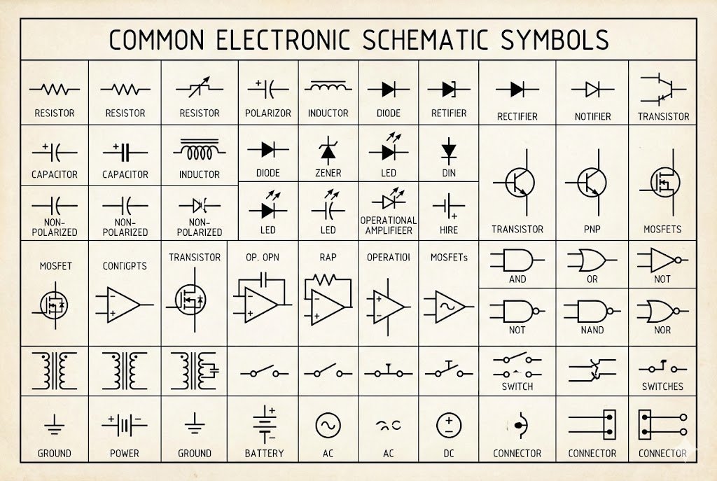
To design circuits, you must know symbols for resistors (zigzag lines1), capacitors (parallel lines2), inductors (coils3), power sources4 (circles/batteries), ground (triangles/lines), diodes (triangles with a line), and transistors (three-terminal symbols). These represent the core functions of any electronic system.
I remember my first time looking at a professional schematic. It was a mess of lines and strange icons. I felt completely lost. But once I learned to recognize the key symbols, it was like a new world opened up. Understanding these symbols is the first step to becoming confident with electronics. It turns a confusing map into a clear set of instructions. Let's break down the most important symbols you need to know, so you can start reading and designing circuits with ease.
How Do You Read Symbols for Basic Components Like Resistors and Capacitors?
Trying to figure out what each little symbol means can stop your project cold. It's tough when you know what you want to build but the schematic looks like gibberish.
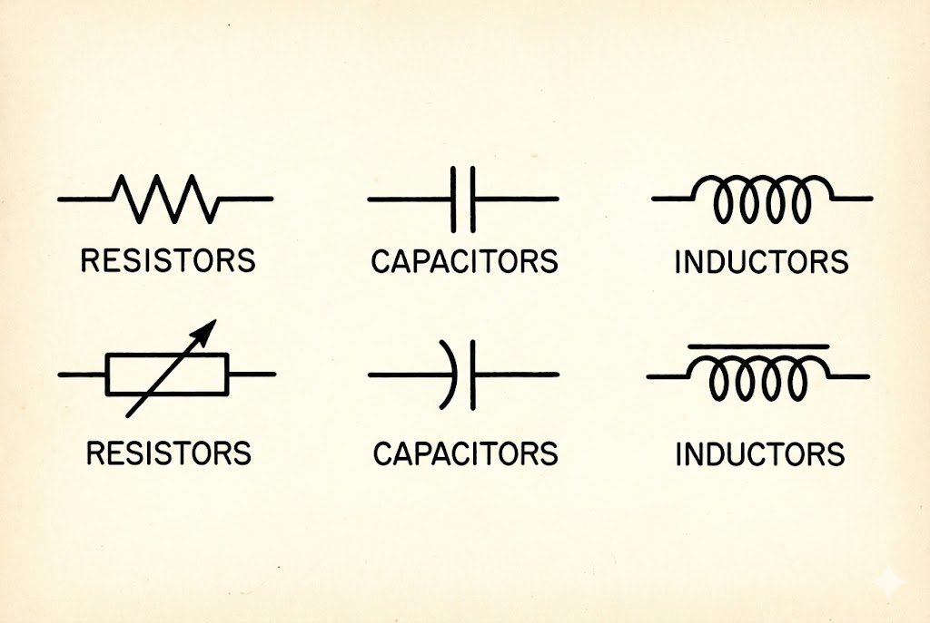
Resistors are shown as zigzag lines1 (US) or rectangles (IEC). Capacitors are two parallel lines2, sometimes with one curved. Inductors are represented by a series of loops or coils3. These symbols show the component's function in the circuit.
When I started in this industry over 20 years ago, mastering these basic symbols was my first real test. It felt like learning the alphabet. Without it, you can't read words or build sentences. The same is true for electronics. These symbols for passive components are the foundation. They control the flow of electricity, store energy, and manage magnetic fields. Getting them right is not just about drawing a pretty picture; it's about making sure your circuit actually works. Let’s look at each one more closely.
Resistors: Controlling the Flow
Resistors are fundamental. Their job is to limit the flow of current. The most common symbol in North America is a zigzag line. In Europe and other parts of the world, following the IEC standard, it's a simple rectangle. Sometimes you'll see a number next to it, like "10k," which means 10 kilohms. A variable resistor, or potentiometer5, adds an arrow through the symbol to show it can be adjusted.
Capacitors: Storing Energy
Capacitors store electrical energy in an electric field. The basic symbol is two parallel lines2. If the capacitor is polarized, meaning it has a positive and a negative side, one of the lines will be curved or have a plus sign. Getting the polarity wrong on something like an electrolytic capacitor can make it fail, sometimes spectacularly. I learned that lesson the hard way in an early project.
Inductors: Resisting Change
Inductors store energy in a magnetic field when current flow6s through them. Their symbol looks like a series of coils3, which makes sense because that's how they are often built. They are used in filters, oscillators, and power converters.
| Component | US Symbol (IEEE) | International Symbol (IEC) | Function |
|---|---|---|---|
| Resistor | Zigzag Line | Rectangle | Limits or resists the flow of current. |
| Capacitor | Parallel Lines | Parallel Lines | Stores electrical energy. |
| Inductor | Coiled Line | Filled Rectangle/Coiled Line | Stores energy in a magnetic field. |
Why Are Power and Ground Symbols So Critical in a Schematic?
You build a circuit, but it doesn't work. You check every connection, but the problem might be something you overlooked: a missing or incorrect power or ground connection.
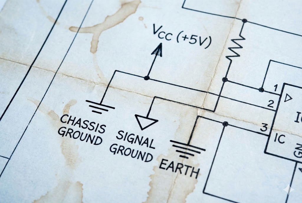
Power symbols (like VCC or a battery icon) show where the circuit gets its energy. Ground symbols (like a triangle or horizontal lines) provide a common reference point (0V) for all signals, ensuring stability and safety.
In my experience sourcing components for OEMs, I've seen countless designs. The best ones are always crystal clear about power and ground. It's not the most exciting part of the design, but it's the most important. A circuit without a clear power source is like a car without an engine. And a circuit without a solid ground connection is like a building with no foundation. It's unstable and unreliable. These symbols aren't just for looks; they define how the entire system operates and how signals are measured. Let's dive into why they are the true backbone of any schematic.
Power Sources: The Heart of the Circuit
Every circuit needs power to function. The symbols for power sources4 tell you where that energy comes from. A simple DC voltage source7 can be shown as a circle with a "+" and "-" sign. A battery is often drawn as a series of long and short parallel lines2. In digital circuits, you'll often see labels like VCC, VDD, or +5V to indicate a positive voltage rail. These labels act as net ports, meaning all points with the same label are connected, even if there isn't a visible line drawn between them. This keeps the schematic clean and easy to read.
Grounding: The Foundation of Stability
The ground symbol is the reference point for all voltages in the circuit. It's considered to be at zero volts (0V). There are several types of ground symbols8, and they mean different things. The earth ground9 symbol (a downward-pointing triangle with horizontal lines) indicates a physical connection to the earth, which is important for safety. The chassis ground10 symbol connects to the metal frame of the device. The most common one, digital or signal ground11 (a simple downward-pointing triangle), is just the 0V reference for the circuit. Using the right ground symbol and ensuring all grounds are properly connected prevents noise and ensures the circuit behaves predictably.
| Symbol Type | Common Representation(s) | Meaning |
|---|---|---|
| DC Voltage Source | Circle with +/-, Battery Symbol | Provides a constant voltage to power the circuit. |
| AC Voltage Source | Circle with a Sine Wave | Provides a fluctuating voltage, typical for household power. |
| Earth Ground | Lines of decreasing length | A physical connection to the Earth, used for safety. |
| Chassis Ground | Fork-like symbol | A connection to the metal frame or chassis of the equipment. |
| Signal Ground | Downward-pointing triangle | The common 0-volt reference point for signals within the circuit. |
What Do the Symbols for Diodes and Transistors Actually Mean?
You see arrows and strange three-legged symbols in a schematic. It's confusing. Without knowing what they do, you can't understand how the circuit controls electricity.
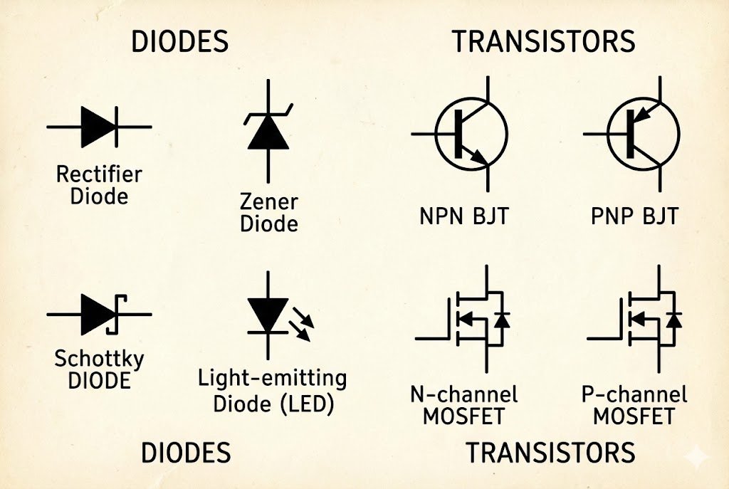
A diode symbol12 (a triangle pointing at a line) shows it allows current to flow in one direction only. A transistor symbol13 (three terminals) represents a component that can amplify a signal or act as an electronic switch.
Semiconductors are the "brains" of modern electronics. When I first started working with them, it was a huge leap from simple resistors and capacitors. Diodes act as one-way gates for current, and transistors are the switches and amplifiers that make everything from your phone to your car's computer work. The symbols might look abstract, but they are incredibly descriptive. The arrow in a diode symbol12 literally points in the direction of conventional current flow6. The different parts of a transistor symbol13 show you exactly how it's connected. Let's break them down.
Diodes: The One-Way Street
The standard diode symbol12 is a triangle pressed against a line. The triangle represents the anode (positive side) and the line represents the cathode (negative side). Current flows from the anode to the cathode. The arrow in the symbol makes this easy to remember. There are special types of diodes, too. A Zener diode14 has a little "Z" shape on the cathode line and is designed to allow reverse current at a specific voltage. A Light Emitting Diode15 (LED) symbol adds two small arrows pointing away from it, showing that it gives off light.
Transistors: The Amplifiers and Switches
Transistors are the workhorses. The two main types are Bipolar Junction Transistors16 (BJTs) and Metal-Oxide-Semiconductor Field-Effect Transistors17 (MOSFETs).
- BJT Symbol: It has three terminals: base (B), collector (C), and emitter (E). The symbol has a line for the base and two angled lines for the collector and emitter. The emitter has an arrow. If the arrow points out, it's an NPN transistor. If it points in, it's a PNP transistor. The arrow shows the direction of current.
- MOSFET Symbol: It also has three terminals: gate (G), drain (D), and source (S). The gate is drawn as a line separated from the main channel, showing it's insulated. The arrow on the source indicates the channel type (N-channel vs. P-channel).
Understanding these symbols is key to troubleshooting or designing any circuit with logic or amplification.
| Component | Symbol Description | Key Function |
|---|---|---|
| Diode | Triangle pointing to a line. Arrow shows current flow6. | Allows current to flow in one direction only. |
| LED | Diode symbol with two arrows pointing away. | Emits light when current flow6s through it. |
| BJT (NPN) | Base, Collector, and Emitter. Arrow on emitter points out. | A current-controlled switch or amplifier. |
| MOSFET (N-ch) | Gate, Drain, and Source. Arrow on body points in. | A voltage-controlled switch or amplifier, very efficient. |
Conclusion
Mastering these essential schematic symbols is the first step. It transforms confusing diagrams into clear instructions, empowering you to design, build, and troubleshoot any electronic circuit with confidence.
Understanding zigzag lines is crucial for identifying resistors in schematics, a fundamental component in electronics. ↩
Parallel lines indicate capacitors, essential for energy storage in circuits, making this knowledge vital for any electronics project. ↩
Coils symbolize inductors, which are key for energy storage and filtering in circuits, crucial for effective design. ↩
Power source symbols are vital for understanding where energy comes from in a circuit, ensuring proper functionality. ↩
Potentiometers are adjustable resistors, and knowing their symbol is key for designing variable circuits. ↩
Understanding current flow is fundamental for troubleshooting and designing effective electronic circuits. ↩
Recognizing DC voltage source symbols is essential for identifying power supply points in electronic designs. ↩
Ground symbols provide a reference point for voltages, essential for circuit stability and safety. ↩
The earth ground symbol is critical for safety in electronic designs, ensuring proper grounding. ↩
Chassis ground symbols indicate connections to the device's frame, important for safety and noise reduction. ↩
Signal ground symbols are essential for establishing a common reference point in circuits, ensuring accurate signal processing. ↩
Diode symbols are crucial for understanding current flow direction, a key concept in circuit design. ↩
Transistor symbols indicate amplifiers and switches, fundamental components in modern electronics. ↩
Zener diodes are important for voltage regulation, and knowing their symbol helps in circuit design. ↩
LED symbols indicate light-emitting components, essential for various applications in electronics. ↩
Understanding BJTs is essential for circuit design, as they play a key role in amplification and switching. ↩
MOSFETs are vital for efficient switching in circuits, making their understanding crucial for modern electronics. ↩