Are you struggling to choose between NMOS and PMOS for your circuit? Picking the wrong one can ruin your design. I will show you how to choose correctly.
NMOS uses electrons1 to carry current and turns on with a positive gate voltage2. PMOS uses holes3 and turns on with a negative gate voltage4. NMOS is faster and cheaper, making it great for low-side switching5. PMOS is better for high-side switching6 because it simplifies the driving circuit.

I remember a time early in my career when a simple MOSFET choice caused a huge delay in our production line. I used an NMOS where a PMOS was needed. The circuit did not work at all. Our team spent three full days finding the bug. We had to redesign the board and order new parts. This cost us money and time. At Nexcir, we see hardware engineers face this same issue often. We supply parts to many OEM and ODM teams. We know that picking the right component is the first step to success. Let us dive into the details so you do not make the same mistake.
How Does Vgs Turn-on Voltage Differ Between NMOS and PMOS?
Do you get confused by gate-to-source voltage requirements? Applying the wrong voltage can fry your components. Let us look at the exact Vgs rules for both types.
To turn on an NMOS, you must apply a positive Vgs. The gate voltage must be higher than the source. To turn on a PMOS, you need a negative Vgs. The gate voltage must be lower than the source voltage.

Understanding Gate Control
The gate-to-source voltage is called Vgs. This voltage acts like a key. It opens the door for current to flow. For an NMOS, the source connects to the ground. You need a positive voltage at the gate to open the door. For example, applying 5V to the gate turns the NMOS on. For a PMOS, the source connects to the power supply. You need a negative voltage relative to the source to open its door. If the source is at 12V, the gate needs to be at a lower voltage, like 0V, to turn on. I always tell my clients to check the datasheet for the exact Vgs threshold.
Understanding MOSFET Symbols
The schematic symbols7 for NMOS and PMOS look different. You must know how to read them. The NMOS symbol has an arrow pointing inward toward the gate. The PMOS symbol has an arrow pointing outward away from the gate. This arrow shows the direction of the body diode. I always check the arrow direction first when I look at a new circuit diagram. This simple check saves a lot of time.
Why Electrons and Holes Matter
The difference in Vgs comes from the physical structure of the silicon. NMOS uses electrons1 to move current. Electrons are very light and move fast. This makes NMOS faster and more efficient. PMOS uses holes3 to move current. Holes are just empty spaces left by electrons. They move much slower. Because of this, PMOS transistors are usually larger and cost more than NMOS transistors with the same rating.
| Feature | NMOS | PMOS |
|---|---|---|
| Turn-on Vgs | Positive | Negative |
| Schematic Arrow | Points Inward | Points Outward |
| Charge Carrier | Electrons | Holes |
| Switching Speed | Faster | Slower |
| Cost | Lower | Higher |
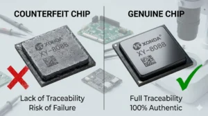
Our team at Nexcir has over 20 years of experience. We know how important these details are. We help OEM and ODM procurement managers find the exact parts they need. We make sure every component is 100 percent original. Counterfeit parts often have wrong Vgs thresholds. This will cause your circuit to fail. We protect you from this risk.
Why Do We Use NMOS for Low-Side and PMOS for High-Side Driving?
Is your load not getting power correctly? Placing a MOSFET on the wrong side of the load causes major switching failures. Here is how to place them right.
We use NMOS for low-side driving because its source connects directly to ground. This makes the positive gate control very simple. We use PMOS for high-side driving because its source connects to the power supply. This allows a simple low-voltage signal to turn it on.

The Basics of Low-Side Switching
Low-side switching means you place the switch between the load and the ground. The load connects to the positive power supply. NMOS is the best choice here. The NMOS source connects right to the ground. The ground is 0V. So, a simple positive signal from a microcontroller can easily turn the NMOS on. I see many engineers use NMOS for motor control and LED driving. It is cheap and easy to use.
The Basics of High-Side Switching
High-side switching means you place the switch between the positive power supply and the load. The load connects to the ground. PMOS is the best choice here. The PMOS source connects directly to the power supply. To turn it on, you just pull the gate voltage down to ground. If you try to use an NMOS for high-side switching6, the source voltage will float. You will need a complex charge pump circuit to boost the gate voltage higher than the power supply. PMOS avoids this problem completely.
| Driving Type | MOSFET Type | Switch Location | Source Connection | Gate Control |
|---|---|---|---|---|
| Low-Side | NMOS | Between Load and Ground | Ground (0V) | Positive Voltage |
| High-Side | PMOS | Between Power and Load | Power Supply | Ground (0V) |
Hardware engineers in the automotive and industrial sectors often need stable high-side switches. I work with many production teams who need reliable PMOS parts. At Nexcir, we understand these pain points. We supply 100 percent authentic electronic components. We have a global supply network. We can deliver these parts on time to keep your production schedule stable. We also help customers find alternatives for end-of-life components. If your favorite PMOS is out of stock, we will find a perfect replacement. We ensure the new part has the exact same Vgs and current rating.
Which Logic-Level MOSFETs Are the Best for Your Current Design?
Are you having trouble finding reliable logic-level MOSFETs8? Fake parts and stock shortages can stop your production line. I will share some top choices you can trust.
Popular logic-level NMOS options include the IRLZ44N9 and AO340010. For PMOS, the AO340111 and FDN338P12 are great choices. These parts switch fully on at low voltages like 3.3V or 5V. They are perfect for microcontrollers in automotive and IoT devices.

Top NMOS Recommendations
Modern circuits use microcontrollers that run on 3.3V or 5V. Standard MOSFETs need 10V to turn on fully. Logic-level MOSFETs solve this problem. They turn on completely with just 3.3V or 5V. The IRLZ44N9 is a very popular logic-level NMOS. It can handle high current and works well for motors. Another great option is the AO340010. It is a surface-mount part. It is very small and perfect for IoT devices. I always recommend these to my clients.
Top PMOS Recommendations
For PMOS, the AO340111 is a favorite among hardware engineers. It pairs perfectly with the AO340010. It is great for battery management circuits. The FDN338P12 is another excellent logic-level PMOS. It offers low resistance and high efficiency. Automotive circuits need very tough components. They must handle high heat and voltage spikes. We ensure all our automotive MOSFETs meet strict industry standards.
| Part Number | Type | Package | Typical Application |
|---|---|---|---|
| IRLZ44N9 | NMOS | TO-220 | Motor Control |
| AO340010 | NMOS | SOT-23 | IoT Devices |
| AO340111 | PMOS | SOT-23 | Battery Management |
| FDN338P12 | PMOS | SuperSOT-3 | Load Switching |
Procurement managers often worry about finding these popular parts. Market prices fluctuate. Counterfeit parts are everywhere. Our team at Nexcir solves these problems. We source these exact components from authorized distributors and original manufacturers. We offer stable pricing. We provide global logistics to make sure you get your parts safely. You can trust us to lower your procurement risks and enhance your overall competitiveness.
Conclusion
NMOS and PMOS have different Vgs rules and switching roles. Knowing these differences helps you design better circuits. Nexcir is always here to supply your authentic electronic components safely.
Understanding the benefits of NMOS using electrons can help you choose the right component for faster and more efficient circuit designs. ↩
Learning about positive gate voltage's role in NMOS operation can prevent design errors and ensure proper circuit functionality. ↩
Exploring why PMOS uses holes can provide insights into its slower speed and higher cost, aiding in informed component selection. ↩
Understanding negative gate voltage's effect on PMOS can help you avoid common mistakes in high-side switching applications. ↩
Discovering why NMOS is ideal for low-side switching can simplify your design process and improve circuit efficiency. ↩
Exploring PMOS's suitability for high-side switching can enhance your design strategy and prevent switching failures. ↩
Knowing the differences in schematic symbols can save time in circuit analysis and prevent design errors. ↩
Finding reliable logic-level MOSFETs can ensure compatibility with microcontrollers and prevent production delays. ↩
Learning about the IRLZ44N can help you choose a robust NMOS for high-current applications like motor control. ↩
Exploring the AO3400's features can guide you in selecting a compact and efficient NMOS for IoT applications. ↩
Understanding the AO3401's suitability for battery management can enhance your design's reliability and efficiency. ↩
Discovering the benefits of the FDN338P can help you select a PMOS with low resistance and high efficiency for load switching. ↩